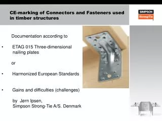
Timber Structures
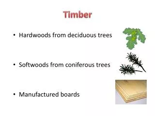
Timber Structures. Sawn Lumber Glulam Plywood. Sawn Lumber. Highly variable Classified by grade Visually or Mechanically graded Grade depends on number and location of defects Defects – shakes, checks, splits and knots.

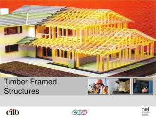
Timber Structures
E N D
Presentation Transcript
Timber Structures • Sawn Lumber • Glulam • Plywood
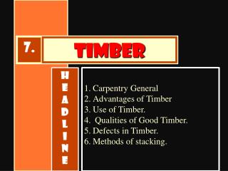
Sawn Lumber • Highly variable • Classified by grade • Visually or Mechanically graded • Grade depends on number and location of defects • Defects – shakes, checks, splits and knots
Sawn Lumber is available in lengths up to 20’ to 25’ with the following cross sectional dimensions:
Glulam • Composed of strips of sawn lumber glued together • Can form larger sections than can be obtained from trees • Can optimize placement of wood
Glulam Member can be any length that can be shipped in the following cross-sections:
Plywood • Made from sheets of wood peeled from logs • Glued together to from large panels • Typically 4’ by 8’ • Available in ¼” to 1 1/8” thicknesses • Use American Plywood Association literature for strengths
Allowable Stress Design of Timber • ASD design still in use in timber • Service load stress ≤ allowable stress The allowable stress depends on the species and grade. The following table gives allowable stress values in psi:
Allowable Stress Adjustment Factors Adjustment Factors are used to modify the allowable stress for various use conditions. The following table lists the adjustment factors and their applicability:
Timber Beam Design Example p. 7 notes Consider a wood frame house with dimensions shown. The first floor will be supported by joists 16” c.c., which, in turn, will be supported on wood sills on basement walls at the exterior, and on spine beams on the interior. The spine beams, in turn, will be supported on columns placed 20’ c.c. in order to leave maximum clear space in the basement. Service live load will be assumed as 40 psf, and service dead load, 15 psf. We will assume plywood structural flooring, and No. 2 Southern Pine for the joists and spine beam. The self weight of the joists and spine beams will be assumed to be included in the dead load.
Floor Plan 60’-0 c.c. joists@16”c.c 20’-0 c.c. Spine beam 20’-0 c.c. 20’-0 c.c. 20’-0 c.c.
Adjustment Factors CD = Load Duration Factor = 1.0 for maximum intensity live load for 10 years, p. 3 notes CM Ct
Adjustment Factors CL – Beam Stability Factor – for sawn lumber only, CL = 1.0 for the following conditions (d and b are nominal dimensions): • d ≤ 2b → no lateral support required (2x4) • d ≤ 4b → both ends held in position to prevent overturning (2x8) • d ≤ 5b → one edge of beam laterally supported for entire length. (2x10) • d ≤ 6b → compression edge laterally supported for entire length… (2x12) • d ≤ 7b → both edges continously laterally supported (2x14) If these conditions are not met CL must be calculated (eq. p. 6 notes).
Adjustment Factors CF - Size Factor CV – Volume Factor – Only applies to Glulam, p. 3 notes Typ. Cfu – Flat use Factor – allowable stress factors are based on loading the narrow edge. Flat use factor modifies the allowable stress when the load is applied to the wide face. Flat use
Adjustment Factors • Cr – Repetitive use factor – For sawn lumber whenever three or more beams in contact or not more than 24” c.c. share a load Cr = 1.15 • Cc – Curvature factor – applies only to glulam • Cf – Form factor – For circular or diamond shape cross-sections • CH –Shear Stress Factor – Can increase allowable shear stress of beam if location and extent of defects is known
Detail of Beam Resting on Sill • Critical shear for design is a distance d from face of support 20’-0 2 x 12 joist d 2 x 6 wood sill d basement wall
Can consider composite section when calculating deflection if sub- floor is properly connected to joists plywood flange 2 x 12 joist
Floor Plan 60’-0 c.c. joists@16”c.c 20’-0 c.c. Spine beam 20’-0 c.c. 20’-0 c.c. 20’-0 c.c. Spine beam showing loading from joists
Cp = Column stability factor • CD = 1.0 for continuous lateral support • CD≤ 1.0 no intermediate lateral support equation p. 6 notes
Southern Pine Span Tables • What is the maximum span for Grade 2, 2 x 10 floor joists, spaced 16” c.c., carrying 40 psf live load? • Choose a ceiling joist to carry a live load of 20 psf for a span of 15 ft. The joist will be spaced at 24” c.c. • An existing floor system is composed of Grade 1, 2 x 12’s, spaced 12” c.c. The joists span 14 ½’. What is the maximum allowable live load based on the Southern Pine Span Tables?
Biaxial Bending of Beams Example • Choose a W-shape beam for the factored loading shown using grade 36 steel. The simple beam span is 25 feet and it is continuously braced against instability. It is not necessary to check shear and deflection for this problem. 4 5 2 k/ft 3 3 k/ft