Download
1 / 1
10 likes | 131 Views
Learn a flexible method using FastCap program to determine air gap and leakage flux reluctances. The method enhances accuracy and speed in inductance value calculations when modeling core reluctances. Compare various methods in three examples and optimize inductive component designs.

E N D
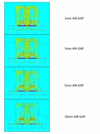
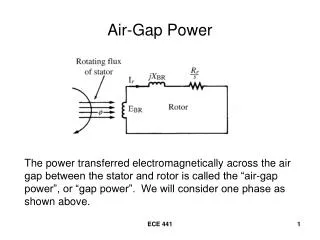
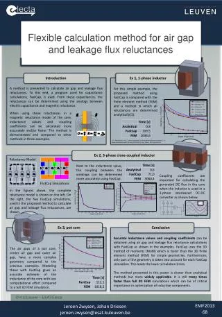
Flexible calculation method for air gap and leakage flux reluctances Introduction Ex 1, 1-phase inductor A method is presented to calculate air gap and leakage flux reluctances. To this end, a program used for capacitance calculations, FastCap, is used. From these capacitances, the reluctances can be determined using the analogy between electric capacitance and magnetic reluctance. For this simple example, the proposed method using FastCap is compared with the finite element method (FEM) and a method in which all reluctances are determined analytically(1). When using these reluctances in a magnetic reluctance model of the core, inductance values and coupling coefficients can be calculated more accurately and/or faster. The method is demonstrated and compared to other methods in three examples. (1) J. Muhlethaler et al., "A novel approach for 3d air gap reluctancecalculations," in Power Electronics and ECCE Asia (ICPE & ECCE), Jeju, Korea, 2011, pp.446-452 Ex 2, 3-phase close-coupled inductor Reluctance Model Next to the inductance value, the coupling between the windings can be determined more accurately using FastCap. Coupling coefficients are important for calculating the generated DC flux in the core when the inductor is used in a 3-phase interleaved DC-DC converter as shown below. FastCap Simulations In the figures above, the complete reluctance model is shown on the left. On the right, the five FastCap simulations, used in the proposed method to calculate air gap and leakage flux reluctances, are shown. Ex 3, pot core Conclusion Accurate inductance values and coupling coefficients can be obtained using air gap and leakage flux reluctance calculations with FastCap as shown in the examples. FastCap uses the 3D method of moments (MoM) which is faster than the 3D finite element method (FEM) for simple geometries. Furthermore, only part of the geometry is taken into account for each FastCap simulation. This leads the lower simulation times. The method presented in this poster is slower than analytical methods but more widely applicable. It is still many times faster than full 3D FEM simulations which can be of critical importance in optimization of inductive components. • The air gaps of a pot core, center air gap and outer air gap, have a more complex geometry compared to the previous examples. Modeling these with FastCap gives an accurate estimate of the inductance of the core with less computational effort compared to a full 3D FEM simulation. EMF2013 68 JeroenZwysen, Johan Driesen jeroen.zwysen@esat.kuleuven.be