Download
1 / 33
370 likes | 603 Views
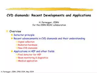
CVD diamonds: Recent Developments and Applications H. Pernegger, CERN for the CERN RD42 collaboration. Overview Detector principle Recent advancements in CVD diamonds and their understanding Signal collection Radiation hardness New CVD diamonds Applications in HEP and other fields

E N D
CVD diamonds: Recent Developments and ApplicationsH. Pernegger, CERN for the CERN RD42 collaboration • Overview • Detector principle • Recent advancements in CVD diamonds and their understanding • Signal collection • Radiation hardness • New CVD diamonds • Applications in HEP and other fields • Pixel detector for HEP • Beam monitoring & diagnistics • Medical application
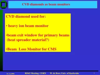
Motivation to use CVD diamonds • Use at LHC/SLHC (or similar environments) • Precision tracking at inner layer required • Must survive the radiation levels typically present at small radia • Material properties • Radiation hard (no frequent replacements) • Fast signal collection time • Compact + low Z solid state detector • Room temperature operation • Basic types of material • Poly-crystalline CVD diamond (pCVD) • Single-crystal CVD diamond (scCVD)
Low dielectric constant- low capacitance High bandgap - low leakage current Fast signal collection Mip signal only 50% of Silicon for same radiation length Collection efficiency <100% (pCVD) Basic material constants in comparison
Basic Principle of Operation • “Solid state Ionization chamber” • Contacts both sides • No doping or junction required • “planar” • Structured electrodes with sizes from mm to cm • Signal • Typically use integrated amplifiers for readout • Collection distance d = mEt • Measured charge Q = d/t Q0
Characterization of CVD diamonds • Measure charge collection distance (through integrating amplifiers) • pCVD diamond “pumps” : signal increase by a factor 1.5-1.8 • Filling of charge traps • Contacts: Cr/Au, Ti/W, Ti/Pt/Au • Use dots -> strip -> pixel on same diamond (contacts can be removed) • Typically use 1V/mm as operation point
CVD diamonds • Growth side pCVD diamonds wafer grown up to 5 inch • RD42 in research project with Element Six Ltd to increase charge collection distance in pCVD diamond material
Collection distance on recent pCVD diamonds • Now reach signals of 9800 e- mean charge • Most probable signal 8000e- • CCD = 275mm • Research program worked • Diamond available in large sizes
Irradiation studies: Protons up to 2.2 x 10¹⁵ /cm2 • Signal (or SNR) and spatial resolution before and after irradiation • Signal decrease starts at 2 x 10¹⁵ /cm2 • Resolution 11mm (before) to 7.4mm (after) • Measured on 50mm pitch strip detector
New type of CVD diamond: CVD Single Crystals • Motivation: Avoid defects and charge trapping present in pCVD diamonds • remove grain boundaries (homogeneous detector) • Reduce (or eliminate) charge trapping • Signal distribution in a single crystal CVD diamond [Isberg et al., Science 297 (2002) 1670]
Single Crystal CVD diamonds • HV and pumping characteristics Full signal at 0.2 V/mm No pumping • Current work with single crystals in cooperation with Element Six • Improve sample “engineering” (reduce variation)
Single Crystal : Trancient Current Measurements (TCT) • Measure charge carrier properties important for signal formation • electrons and holes separately • Use a-source (Am 241) to inject charge • Injection • Depth about 14mm compared to 470mm sample thickness • Use positive or negative drift voltage to measure material parameters for electrons or holes separately • Amplify ionization current a Electrons only Or Holes only V
Ionization current in a sample of scCVD diamond • Extracted parameters • Transit time • Velocity • Pulse shape • Transit time of charge cloud • Signal edges mark start and arrival time of drifting charge cloud • Error-function fit to rising and falling edge • Total signal charge t_c
Preliminary measurement of velocity on a single crystal • Average drift velocity for electrons and holes • Extract m0 and saturation velocity • m0 for this sample: • Electrons: 1714 cm2/Vs • Holes: 2064 cm2/Vs • Saturation velocity: • Electrons: 0.96 107 cm/s • Holes: 1.41 107 cm/s
Preliminary carrier lifetime measurements • Extract carrier lifetimes from measurement of total charge • Lifetime: >35 ns for electrons and holes -> larger than transit time • Charge trapping doesn’t seems to limit signal lifetime -> full charge collection (for typical operation voltages and thickness)
Applications of CVD diamonds • In general CVD diamond is used as detector material in several fields • HEP and nuclear phyics • Heavy ion beam diagnostics • Synchroton radiation monitoring • Neutron and a detection …. • (Short) Selection of Applications in this presentation • Pixel detector developments using CVD diamond detector • Beam Conditions Monitoring (e.g. at LHC) • Beam diagnostics for radiotheraphy with proton beams
Application I:Pixel Detectors with ATLAS & CMS FE chips • Use present implementation of radhard FE chips together with pCVD (later possible scCVD) diamonds • Bumpbonding yields ≈ 100% now
Test assembly Underbump metalization Preparation of pixel test assembly SiLab/ Bonn
Example: FE chip with pCVD diamond • Source & Testbeam results with pCVD diamond mounted to Atlas Pixel chip M. Keil / SiLab/ Bonn • Spatial resolution (pad size = 50x400mm)
“DC current” Uses beam induced DC current to measure dose rate close to IP Benefits from very low intrinsic leakage current of diamond Can measure at very high particle rates Simple DC (or slow amplification) readout Examples: See talk by M.Bruinsma for BaBar Similar in Belle Similar method planned for CMS Single particle counting Counts single particles Benefits from fast diamond signal Allows more sophisticated logic coincidences, timing measurements Used at high particle rates up to Requires fast electronics (GHz range) with very low noise Examples CMS and Atlas Beam conditions monitor Application II: Beam Conditions Monitoring • Common Goal: measure interaction rates & background levels in high radiation environment • Input to background alarm & beam abort
Beamloss scenario: study for CMS (1) • E.g. accidental unsynchronized beam abort • Instantaneous , difficult to protect against Unsynchronised beam abort: ~1012 protons lost in IP 5 (CMS) in 260ns (M. Huhtinen, LHC Machine Protection WG, Oct. 2003)
Beamloss scenario: study for CMS (2) • E.g. Loss of protons on collimators close to experiments (“TAS”) • Worse in dose rate (>up to 1000 x unsynchronized abort if consecutive bunches are lost) • Slower (several turns) therefore possible to protect against if early signs are detected (dose [Gy]) (M. Huhtinen, LHC Machine Protection WG, Oct. 2003)
CMS tests with Cern PS fast beam extraction 2 Diamonds PS beam monitor • Single pulses from diamond • Bias on Diamond = +1 V/um • Readout of signal: • 16m of cable • no electronics • 20dB attenuation on signal cable (factor 10) A. MacPherson et al. / CMS-BCM Almost identical diamond response to PS beam monitor response (pulse length 40ns) Diamond signal current is 1-2 A !
12ns Time difference Atlas Beam Conditions Monitoring • Time-Of-Flight measurement to distinguish collisions from back ground during normal running • Located behind pixel disks in pixel support tube Need to measure single MIPs radiation hard! … and very fast: rise time <1ns, width <3ns
Atlas BCM: single-MIP detector with <1ns rise time • Different versions of FE electronics (Fotec/Austria) • 500Mhz (40 dB) (2 stages) • 1 Ghz (60 dB) (3 stages) • 2 pCVD diamond detector back-to-back • w =360 µm, CCD ~ 130 µm • HV Bias 2V/mm • Source tests and test beam 90Sr source or 5GeV/c pions (Pb collimator) Diamond on support Scintillator
Preliminary test results • MIP signal (testbeam & Sr90 source) • after 16m of cable • perpendicular to beam, double diamond assembly • Rise time 900ps, FWHM = 2.1ns preliminary SNR = 7.3:1
Conventional X-Ray Therapy Ion-Therapy 1 cm 1 cm Application III: Diamonds in Proton Therapy: • Austrian medical accelerator facility • Cancer treatment and non-clinical research with protons and C-ions Protons C-Ions
Facility Layout • Diamonds used for Beam Diagnostics: • High-speed Counting of single particles in extraction line • Resolve beam time structure Preliminary layout Synchrotron Injector 2 Experimental rooms • Proton & Carbon Beam • Energy: 60-240 MeV protons and 120-400 MeV/u C-ions • Intensity: 1x10¹⁰ protons (1,6 nA) and 4x10⁸ C-ions (0,4 nA) • Beam size: 4x4 mm2 to 10x10 mm2 4 Treatment rooms
trigger measured Testbeam results for Proton Beam Diagnostics • 2 diamond with different pad size + scintilator as “telescopes” tested at Indiana University Cyclotron Facility • 2.5 x 2.5 mm2 (in trigger) CCD = 190 mm, D= 500 mm • 7.5 x 7.5 mm2 (for analog measurements) CCD = 190 mm, D= 500 mm
Signal timing properties • Rise time : 340ps Duration: 1.4ns • Single shot • Average pulse shape
200 MeV 104 MeV 55 MeV Signal/Noise and energy dependence Signal energy dependence SNR • Measured most probable S/N ranges from 15:1 to 7:1
CVD diamonds as radiation hard detectors High quality polycrystalline CVD diamonds (ccd up to 270mm) are readily available now in large sizes Radiation tests showed radiation hardness up to 2 x 10¹⁵ p/cm2 Single crystal CVD diamonds promise to overcome limitations of polycrystalline CVD diamonds Full signal collection already at lower voltages Long charge lifetime Very little charge trapping and uniform detector (no grain boudaries) There are many applications around which benefit from diamond’s intrinsic properties Strip or Pixel detectors for future high luminosity accelerators Beam diagnostics and monitoring Summary
High-bandwidth amplifier for fast signal measurements • Use current amplifier to measure induced current • Bandwidth 2 GHz • Amplification 11.5 • Rise time 350ps • Inputimpedance 45 Ohm • Readout with LeCroy 564A scope (1GHz 4Gsps) • Correct in analysis for detector capacitance (integrating effect) • Cross calibrated with Sintef 1mm silicon diode • m_e = 1520 cm2/Vs • I = 3.77 eV +/- 15%
Irradiation studies: Pions up to 2.9 x 10¹⁵ /cm2 • Signal (or SNR) and spatial resolution before and after irradiation Preliminary results • 50% Signal decrease at approx 3 x 10¹⁵ /cm2 * (TO BE CONFIRMED) • Narrower signal distribution after irradiation • 25% Resolution improvement