Download
1 / 8
80 likes | 217 Views
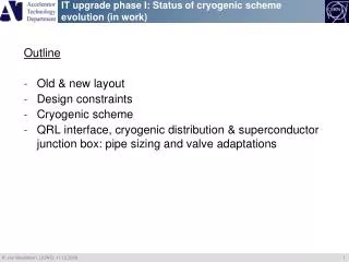
IT upgrade phase I: Status of cryogenic scheme evolution (in work). Outline Old & new layout Design constraints Cryogenic scheme QRL interface, cryogenic distribution & superconductor junction box: pipe sizing and valve adaptations. Old & New, with cold D1, inner triplet layout in IP1 & IP5.

E N D
IT upgrade phase I: Status of cryogenic scheme evolution (in work) Outline • Old & new layout • Design constraints • Cryogenic scheme • QRL interface, cryogenic distribution & superconductor junction box: pipe sizing and valve adaptations
Cryogenic system: design constraints (1/2) The cooling of the magnets for the Phase-I Upgrade and the associated cold power transfer system will be realized within the boundaries of the existing cryogenic infrastructure: the types and maximum available quantities of cryogens may not exceed the presently available supply provided in IR1 and IR5 by the cryogenic distribution line (QRL) and the respective refrigeration systems. Design pressures of the new equipment are also subject to the present LHC specification. ---------------------------------------------------------------------------------------------------------- The present QRL service modules contain most of the functionalities necessary for the Phase-I Upgrade but possible re-use is limited by: 1) Increasing the piping dimension is prohibitive, 2) The existing valves can be adapted to new requirements by changing their poppets (within reasonable limits). 3) Functionalities exceeding the possibilities of the existing service module would need to be provided by a local cryogenic distribution box. 4) The QRL service module itself should preferably be moved to a new location in between the correctors and D1. Keeping it at its present location would require a dedicated cryogenic extension line with many pipes and high diameters to limit pressure drops. The construction of entirely new service modules should also be considered.
Cryogenic system: design constraints (2/2) Basic flow scheme provides: • D1 cooled by pool boiling • D1 with warm bore (no actively cooled beam screen) • CP + IT cooled by HeII using an internal bayonet HX of ID 95 mm • CP + IT with cold bore and actively cooled beam screen • Cold powering via a link and remote DFX
E F B D C new L&V new L&V QV920 CV920 new new CV930 CV915 CV947 CV950 CV910 QV923 EE LD1 CC’3 FF DH CY2 CS CY1 XB LD2 beam screen TT847 CC’ EH847 LH LH Q3 Q2b Q2a Q3 CP D1 HeII pressurized (1.9 K) HeII saturated (1.9 K) WRL HeI saturated (4.5 K) EH HeI supercritical (4.5 – XX K) HeI supercritical (4.5 – 20 K)
Cryogenic scheme: QRL interfaces (3/3) • XB line needs size increase: 70 95 or 100 (pressure drop) • DH line needs size increase: 20 30 (D1 quench safety) • Two new C-D1 lines: (level control & cool-down/fill/warm-up) • One line redundant (TD) • Cold powering & DFX cooling mode flexible (returning or not to FF, D) The construction of entirely new service modules should be considered.