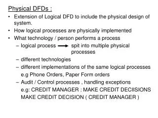
DFDs
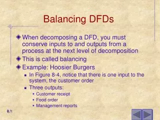
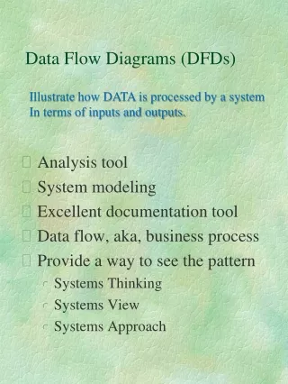
This guide explores the fundamental concepts of Data Flow Diagrams (DFD) within the Software Development Life Cycle (SDLC), focusing on project identification, selection, initiation, and planning. It emphasizes the importance of process identification, system modeling, and functional decomposition using DFDs to detail system interactions and data flows. Key characteristics like leveling, balancing, and the correct representation of processes, data stores, agents, and flows are covered. Real-world examples, like the Cougar Burger case, illustrate the practical application of DFD in project phases.


DFDs
E N D
Presentation Transcript
DFDs Class 11
SDLC Project Identification & Selection Project Initiation & Planning **Analysis** Logical Design Physical Design Implementation Maintenance
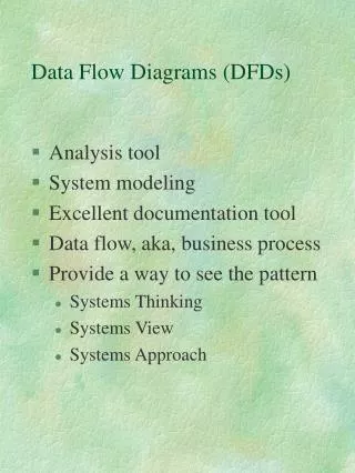
Parts of DFD • External Agent; Source / Sink • Data Store • Process • Data Flow Line
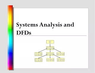
To Model the system • Emphasize process • Identify, hierarchically: • The system • The subsystems/functions of the system • The transactions within a given function
Characteristics of DFD • I-P-O modeling • Leveling of DFDs (explosion) • Balancing of data flows • Shows flow of data not flow of control • Shows set of possible paths (not what causes a path to be taken)
Explosion • Also called Functional Decomposition • An iterative process of breaking the description or perspective of a system down into finer and finer detail. • Context diagram, Level 0 diagram, Level 1 diagrams, etc. • Balancing the levels
What you CAN’T do: • Processes • No input data flow, no output data flow • Data Stores • Data flow directly to another data store • Agents • Data flow directly to another external agent, data flow directly to or from data store • Data Flows • No double arrows, no “break-off” lines defined as something different, no data flow line into another data flow line
Cougar Burger Example • Context Level
Cougar Burger Example • Level 0
Cougar Burger example • Level 1
Identifying DFD parts • Bottom-up and Top-Down
Different types of DFDs • Current vs New