Download
1 / 19
190 likes | 274 Views
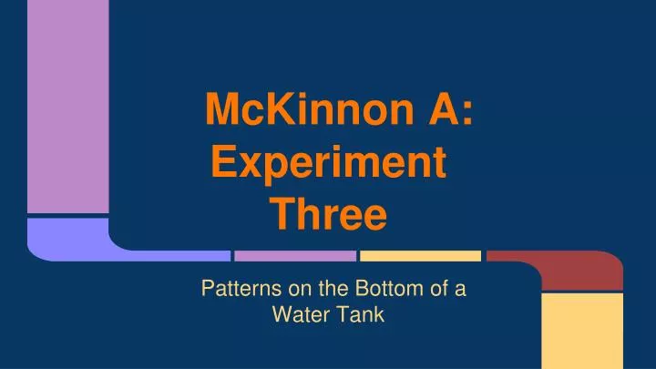
McKinnon A: Experiment Three. Patterns on the Bottom of a Water Tank. Brief. Bright Waves : Illuminate a water tank. When there are waves on the water surface, you can see bright and dark patterns on the bottom of the tank. Study the relation between the waves and the pattern. A quick test.

E N D
McKinnon A:Experiment Three Patterns on the Bottom of a Water Tank
Brief • Bright Waves: Illuminate a water tank. When there are waves on the water surface, you can see bright and dark patterns on the bottom of the tank. Study the relation between the waves and the pattern.
A quick test This light spot is directly under the peak This dark spot is directly under the trough (contrast added for clarity)
A quick conclusion It seems that the light patches in the patterns on the bottom of the container are directly under the peaks of the waves. But why? Well...
Ideas *Prediction: In the previous experiment, if there is a crest in the wave, there will be a bright spot on the bottom. If there is a trough in the wave there will be a dark spot on the bottom. We predict that this is because of the way light refracts between the two different media. *When light refracts as it travels from air into water, it bends towards the normal of the boundary Bright Area Dark Area Bright Area
Aim We want to find the relationship between the ANGLE of the light source and patterns it makes. We will then see if this matches our theory on the previous slide.
Method To test our prediction, we decided to change the direction of the light. If we could trace the rays from each light source to the bright spots and it matched up, it would support our theory. Materials: • 1x 18L (or similar) transparent waterproof plastic container • 1x AC light bulb • 1x clamp for light • 1x something to clamp the light to • 1x plastic sheet for making waves with • 1x camera to capture results
Method SET UP 1. Fill the container to approx 6.5cm of tap water 2. Move the edge of the container 25cm away from a vertical surface you can clamp the light bulb to. 3. Clamp the AC light bulb onto the wall/window/stand. The minimum height we could we could get it was 23.5cm 4. Plug the bulb into the power point and turn on the light TEST 1. Make a wave in the water with a maximum height of approx 8.5 cm. -Thus the amplitude is a constant 2cm 2. Record footage on the camera of the pattern on the bottom of the container 3. Move the light bulb 10cm higher than before and repeat six times
Method ANALYSE: 1. Choose an appropriate frame from the recording that shows light and dark areas 2. Trace this frame, keeping note of the scale of the size of the container. This can be done by printing it or tracing it off the screen 3. With a ruler, dot in five equally spaced points on the surface of the water. 4. Draw it the tangents and normals for these points 5. With a portractor, find the angle that the waves make with the horisontal 7. Find the angle of depression for the direction of light 8. Find the angle of incidence for the light entering water • 9. Find the angle of refraction for the light entering water • 10. With a portractor, draw in the rays of lights • 11. Compare with the actual frames
Finding Results This gives us: sin(i) = n(water) sin(r) n(air) sin(i) = 1.33 sin(r) 1 sin(r) = sin(i) 1.33 This should help us find the angle of refraction for our rays! *refractive index of water found on wikipedia We now have light from different angles creating different patterns on the bottom of the container. But when ray tracing, how do we know the angle that light should bend? SNELL’S LAW sin(i) = n2 sin(r) n1 where i = angle of incidence r = angle of refraction
Finding Results -> Geometry So: i = 90 – tan-1(height of wave / distance horizontally from light) + angle of wave from horizontal The horisontal distance CHANGES for each measurement to take into account that the light rays are not parallel. Also: r=sin-1(sin(i) / 1.33) These are the equations used to find the angles needed.
Results (23.5cm high) Frame from video for light from a bulb 23.5cm high, 25cm from the container, entering water with waves of amplitude 2cm and average height 6.5 cm 32cm (contrast added for clarity)
Results (43.5cm high) Frame from video for light from a bulb 43.5cm high, 25cm from the container, entering water with waves of amplitude 2cm and average height 6.5 cm 32cm (contrast added for clarity)
Results (63.5cm high) Frame from video for light from a bulb 63.5cm high, 25cm from the container, entering water with waves of amplitude 2cm and average height 6.5 cm 32cm (contrast added for clarity)
But wait! There’re errors! • The measuring of angles, drawing of rays, tangents and normals, and tracing was done by hand. • We analysed a 3D situation in 2D. • The amplitude was not always constant. We found it difficult to keep moving water at an amplitude of exactly 2cm • The working out assumes that the wave height is at the mean height, 6.5cm. This COULD mean the rays refract at a different angle. It seems to be fairly accurate though. • Other lights in the room could have created patterns in the container of their own. However the patterns made by the bulb we were testing with were much easier for us and the camera to see because was is much brighter than other lights in the room.
Well, It looks as though the areas on the sketches with rays densly packed match up with the areas on the images with a high intensity of light. Our prediction is supported! … for now…