Download
1 / 34
400 likes | 747 Views
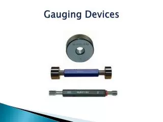
PRESENTATION ON MEASUREMENT AND GAUGING. CONTENTS. A. PRINCIPLE OF OPTICAL INSTRUMENTS B. PRINCIPLE OF PNEUMATIC MEASURING INSTRUMENTS C. PRINCIPLE OF ELECTRICAL MEASURING INSTRUMENTS D. PRINCIPLE OF ELECTRONIC MEASURING INSTRUMENTS E. PRINCIPLE OF MECHANICAL MEASURING INSTRUMENTS.

E N D
CONTENTS A. PRINCIPLE OF OPTICAL INSTRUMENTS B. PRINCIPLE OF PNEUMATIC MEASURING INSTRUMENTS C. PRINCIPLE OF ELECTRICAL MEASURING INSTRUMENTS D. PRINCIPLE OF ELECTRONIC MEASURING INSTRUMENTS E. PRINCIPLE OF MECHANICAL MEASURING INSTRUMENTS
INTRODUCTION • Measuring the dimension of a given component consist of a comparing its dimension with a no standard. • This may be carried out by direct or indirect method.
PRINCIPLE OF OPTICAL INSTRUMENTS • Reflections -: Reflections can be divided into two types: Specular reflection anddiffuse reflection . Specular reflection describes the gloss of surfaces such as mirrors, which reflect light in a simple, predictable way. • When light is incident on a surface, it is partly reflected and partly absorbed in the surface and the remaining part may pass through it.
REFRACTION • When a ray of light travel from one medium into another, it bends while crossing the surface of separation between two media. • The phenomenon of change in path of light as it goes from one medium to another is called refraction.
LAW OF REFRACTION There are two law of refraction -: • The incident ray the normal to the refracting surface at point and the refracted ray all lie in same plane. • The ratio of the sine of angle of incidence to the sine of the angle of refraction is constant
LENSES A lens is a transparent medium bounded by two co-axial curved refracting surface or one covered and one plane surface. Lens are divide two categories -: • Converging lens • Diverging lens
CONVERGING LENS • A convex lens is thicker in the middle and converges a parallel beam of light passing through it to a single point known as the principal focus. • A real image is formed on the screen in this case.0
DOUBLE CONVEX -: when both faces are bulging out. PLANE – CONVEX -: when one face is plan and other is convex. CONCAVE – CONVEX -: when one of the surface is concave and other is convex.
DIVERGING LENS • A concave lens is thinner in the middle and diverges the parallel rays which appear to come from a focal point behind the lens. • A virtual image formed on a screen in case of this type of lens.
PLANO – CONCAVE -: When one of the surface is plane and other is concave. DOUBLE CONCAVE -:When both faces are bulging. CONVEXO – CONCAVE -: When one of the surface is convex and other is concave.
INTERFERENCE • The one of the surface is plane and other is concave. • Interference of light means a phenomenon which involves superposition of two light wave leading to change in their intensity. • It may be define as “ the non-uniform distribution of the energy in the medium due to the superposition of two light waves.”
PRISM A prism is a transparent medium bounded by three rectangular and two triangular plane surface.
OPTICAL PROJECTORS The optical method of measurement are of two general classes-: • Which the object being measured is viewed by a projector or microscope. • Which there is indirect application of opticals.
BASIC ARRANGEMENTS • SOURCE OF LIGHT-: It is a high power electric bulb, which should be placed at the principle focus of the collimating lens. • COLLIMATING LENS -: A collimator lens is used to make the light beams parallel to each other. • PROJECTION LENS -: It is a combination lenses. forms a real image on screen and is placed between projection lens and collimator lens
PRINCIPLE OF PNEUMATIC MEASURING INSTRUMENTS • Pneumatic measuring instruments use to apply a jet of air to the surface being measured and utilized a controlled air pressure as an amplifying medium. • The jet orifice is placed very closed to the surface of the test piece. • The variation in the dimension of work piece affects the escape of air from the aperture and back pressure can be measure.
PRINCIPLE OF ELECTRICAL MEASURING INSTRUMENTS • The mechanical parameters can be measured by the use of electrical means. • This is based of the fact that the use of the electrical parameter are physically related to mechanical parameters of length, mass, time.
ADVANTAGE • Simple operation. • Quick response. • Used under severe working condition. • Having high sensitivity and accuracy.
PRINCIPLE OF ELECTRONIC MEASURING INSTRUMENTS • The electronic instrument have a number of advantage over the mechanical type. • They have little or on moving parts and hence can retain their accuracy over long period. • The accuracy of these instrument is likely to be affected by the temperature and humidity.
AN ELECTRONIC INSTRUMENT CONSIST OF FOUR BASIC UNIT • Measuring probe • Amplifier and indicating unit • Power unit • Base and stand unit
PRINCIPLE OF MECHANICAL MEASURING INSTRUMENTS To reduce the error of measurement the following mechanical magnification are usually used-: • Lever method • Vernier method
LEVER METHOD • The lever is supported on a knife edge support. When a distance ‘l’ is measured by the indicator the magnification ratio is given by: a/b = Reading on the scale/b sinα= a. α/b sinα Where α= angle of displacement corresponding to the measured distance l. • The friction can be reduced by means of specially designed pivots & bearings & making use of knife edges
VERNIERMETHOD • In this method a vernier is used. The vernier principal can also be applied for increasing the accuracy of angular measurement.
It is an additional scale which is used in place of a pointer or indication line on the moveable member & it enables the main fixed scale to be read to a smaller value