Download
1 / 13
130 likes | 347 Views
Plasmonic Imaging for Optical Lithography X-ray Wavelengths at Optical Frequencies Experiments: Progress and Plans Yunping Yang Josh Conway Eli Yablonovitch. The Problem. Classically the resolution limit is determined by the Rayleigh Criterion:

E N D
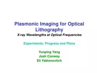
Plasmonic Imaging for Optical Lithography X-ray Wavelengths at Optical Frequencies Experiments: Progress and Plans Yunping Yang Josh Conway Eli Yablonovitch
The Problem Classically the resolution limit is determined by the Rayleigh Criterion: Various schemes have been developed to push this to finer resolution than the wavelength itself, but the scale will always be set by wavelength
Constant Energy Curves By adiabatically tapering the thin film thickness, very small (<50nm) plasmon wavelengths are attainable for in plane imaging. Silver Film on Sapphire p 1.5 eV 400 300 2.0 eV Plasmon Wavelength in nm 200 2.5 eV 100 t 0 20 40 60 80 Silver Film Thickness in nm
Dispersion Relation: Constant Thickness Curves Plasmon Wavelength in nm h 200 100 50 40 30 20 15 10 4 3 t=5nm t=20nm t=2nm t=1nm Plasmon Energy in eV 2 t=thickness of metal film 1 Optical frequencies, but with X-ray wavelengths! 0 k 0 0.1 0.2 0.3 0.4 0.5 0.6 Plasmon Wave-Vector (2/wavelength in nm)
Grating Coupler Grating Silver • Design and fabricate gratings to maximize the coupling efficiency; • Verify the DR with constant thickness; • Find some material parameters Glass
Optical Setup for ATR Coupler Iris Mirror PBS Laser Beam Expander l/2 Lens Sapphire Hemisphere 4f Lens Lens Lens Detector Ag Thin Film 4f
Optical Setup for ATR Coupler • Characterize thin film, such as roughness, thickness; • Experimentally verify the dispersion relation; • Launching a standing wave for Plasmon Wavelength Measurement
A Possible Solution This permits X-ray wavelengths at optical frequencies
Plasmon Wavelength Measurement Resolution: 1.6 nm Antonello Nesci, Rene Dandliker, Hans Peter Herzig, “Quantitative amplitude and phase measurement by use of a heterodyne scanning near-field optical microscope,”Optics Letters, Volume 26, Issue 4, 208-210.
Taper Motivation n9> n8> >n1>n0 Taper design will be a trade between absorption (joule heating), scattering (an adiabatic profile), and maintaining a high enough effective index at all points of propagation to maintain features far-field from conventional lens taper dimple lens out-coupling slot
Criteria It is clear that Loss/ becomes prohibitively large at short wavelengths Thus we change are adiabatic criteria accordingly / = constant Loss/ Wavelength (nm)
Taper Profile 60 50 40 Silver Film Thickness (nm) 30 20 10 100 200 300 400 500 600 Length (nm)