Introduction
90 likes | 719 Views
Introduction. O A. A A. A. B. A. A BA. A B. ω 2. α 2. O 4. O 2. B. Acceleration Polygon for a Four-bar Mechanism

Introduction
E N D
Presentation Transcript
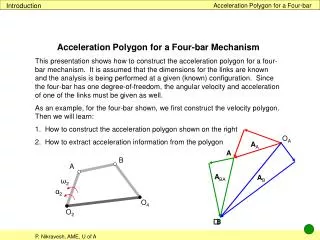
Introduction Acceleration Polygon for a Four-bar OA AA A B A ABA AB ω2 α2 O4 O2 B Acceleration Polygon for a Four-bar Mechanism This presentation shows how to construct the acceleration polygon for a four-bar mechanism. It is assumed that the dimensions for the links are known and the analysis is being performed at a given (known) configuration. Since the four-bar has one degree-of-freedom, the angular velocity and acceleration of one of the links must be given as well. As an example, for the four-bar shown, we first construct the velocity polygon. Then we will learn: How to construct the acceleration polygon shown on the right How to extract acceleration information from the polygon
Example Acceleration Polygon for a Four-bar B A ω2 α2 O4 O2 Example This example shows us how to construct the acceleration polygon for a typical four-bar, such as the one shown on this slide. It is assumed that: all the lengths are known and the four-bar is being analyzed at the configuration shown; the angular velocity and acceleration of the crank are given as well.
Vector loop, differentiation Acceleration Polygon for a Four-bar B RBA Vector loop We follow the same process as we did for the velocity polygon. We first define four position vectors to obtain a vector loop equation: RAO2 + RBA = RO4O2 + RBO4 The first time derivative provides the velocity loop equation: VtA + VtBA = VtB The second time derivative provides the acceleration loop equation: AA + ABA = AB We split each acceleration vector into a normal and a tangential component: A RBO4 RAO2 ► O4 RO4O2 O2 AtA + AnA + AtBA + AnBA = AtB + AnB We need the velocities to calculate some of the accelerations. Therefore we perform a velocity analysis first.
Velocity analysis Acceleration Polygon for a Four-bar B VtA RBA Velocity polygon We calculate VtA: VtA = ω2∙ RAO2 The direction is found by rotating RAO2 90° in the direction of ω2 The direction of VtBA is perpendicular to RBA The direction of VtB is perpendicular to RBO4 Now we construct the velocity polygon Next we determine the angular velocities. We will use these results to calculate the normal components of acceleration vectors. A RBO4 RAO2 ω2 O4 ► RO4O2 O2 ► A VtA ► OV VtBA ► VtB B VtA + VtBA = VtB
Angular velocities Acceleration Polygon for a Four-bar B VtA RBA ω3 Angular velocities The absolute value of the angular velocities are computed as: ω3 = VtBA∕ RBA ω4 = VtB∕ RBO4 RBA has to be rotated 90° cw to head in the direction of VtBA. Therefore ω3 is cw RBO4 has to be rotated 90° ccw to head in the direction of VtB. Therefore ω4 is ccw We will use these results to calculate accelerations. A RBO4 RAO2 ω2 ω4 O4 RO4O2 O2 A ► VtA OV VtBA ► VtB B
Normal components Acceleration Polygon for a Four-bar AtA + AnA + AtBA + AnBA = AtB + AnB B RBA ω3 Normal components We first calculate the magnitude of all the normal components: AnA = ω22∙ RAO2 AnBA = ω32∙ RBA AnB = ω42∙ RBO4 The direction of each normal component of acceleration is opposite to the corresponding position vector A RBO4 RAO2 ω2 ω4 O4 RO4O2 O2 B AnBA A ► AnB AnA O4 O2
Tangential components Acceleration Polygon for a Four-bar AtA + AnA + AtBA + AnBA = AtB + AnB B RBA Tangential components We first calculate the magnitude of AtA: AtA = α2∙ RAO2 The direction is found by rotating RAO2 90° in the direction of α2 We also know that AtBA is on an axis perpendicular to RBA Similarly we know that AtB is on an axis perpendicular to RBO4 A RBO4 RAO2 α2 O4 RO4O2 O2 ► ► B AtA AnBA A ► AnB AnA O4 O2
Acceleration polygon Acceleration Polygon for a Four-bar AtA + AnA + AtBA + AnBA = AtB + AnB Acceleration polygon Now we are ready to draw the acceleration polygon. First we select the origin and add AtA and AnA to obtain AA AnBA is a added at A We also know the axis of AtBA which would be added to AnBA AnB is added to the origin We also know the axis of AtB which would be added to AnB The two lines intersect at B. We complete the acceleration polygon by drawing the missing accelerations Next we determine the angular accelerations. B AtA AnBA A AnB AnA ► ► O4 O2 AtA ► AnA ► OA AA AnB ► AnBA A AB ABA AtBA ► AtB B
Angular accelerations Acceleration Polygon for a Four-bar B α3 RBA Angular accelerations The absolute values of the angular accelerations are computed as: α3 = AtBA∕ RBA α4 = AtB∕ RBO4 RBA has to be rotated 90° cw to head in the direction of AtBA. Therefore α3 is cw RBO4 has to be rotated 90° ccw to head in the direction of AtB. Therefore α4 is ccw This completes the acceleration analysis of this four-bar. A RBO4 RAO2 α4 α2 O4 RO4O2 O2 AtA AnA OA AA ► AnB AnBA ► AB ABA AtBA AtB


