Download
1 / 23
640 likes | 1.53k Views
Introduction to Aeronautical Engineering. Flight Mechanics. The Bottom Line. In normal flight a light aeroplane derives its forward motion from the thrust provided by the engine-driven propeller.

E N D
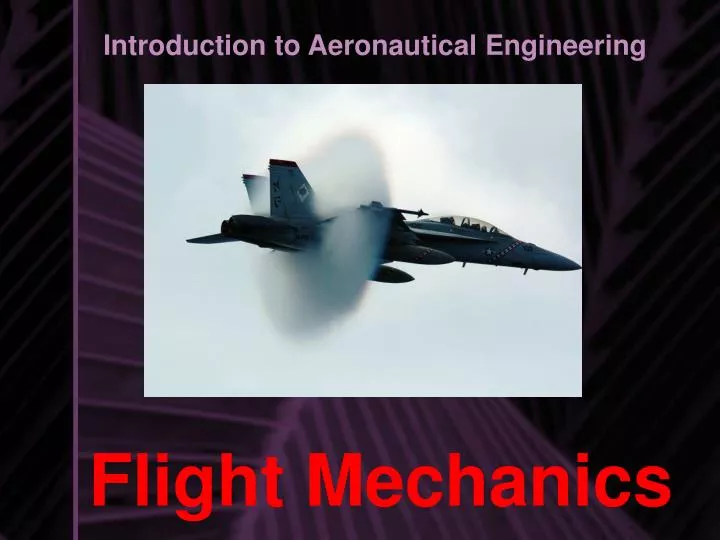
Introduction to Aeronautical Engineering Flight Mechanics
The Bottom Line In normal flight a light aeroplane derives its forward motion from the thrust provided by the engine-driven propeller. If the aircraft is maintaining a constant height, direction and speed then the thrust force will balance the air's resistance (drag) to the aircraft's motion through it. The forward motion creates an airflow over the wings and the dynamic pressure changes within this airflow create an upward acting force or lift, which will balance the force due to gravity – weight – acting downward.
The Bottom Line Thus in normal unaccelerated flight the four basic forces acting on the aircraft are approximately in equilibrium. The pilot is able to change the direction and magnitude of these forces and thereby control the speed, flight path and performance of the aeroplane.
Stagnation and Separation Stagnation Points Air Flow Separation
The property of resisting any change in motion: INERTIA The mass of a body is a measure of its inertia – i.e. its resistance to being accelerated or decelerated by an applied force increases with mass. The unit of mass we will be using is the kilogram [kg]. The air also has mass and thus inertia and will resist being pushed aside by the passage of an aeroplane. That resistance will be felt as pressure changes on the aircraft surfaces.
Airspeed depends on Inertia An aircraft in flight is 'airborne' and its velocity is relative to the surrounding air, not the Earth's surface. When the aircraft encounters a sudden change in the ambient air velocity — a transient gust — inertia comes into play and momentarily maintains the aircraft velocity relative to the Earth or – more correctly – relative to space. This momentarily changes airspeed and imparts other forces to the aircraft. (The fact that inertia over-rides the physics of aerodynamics is sometimes a cause of confusion).
Direction of forces are relative to the flight path Although we said that lift acts vertically upward with thrust and drag acting horizontally, this is only true when an aircraft is in straight and level flight. In fact, lift acts perpendicular to both the flight path and the lateral axis of the aircraft, drag acts parallel to the flight path and thrust usually acts parallel to the longitudinal axis of the aircraft.
Bernoulli's Equation • Points 1 and 2 lie on a streamline, • The fluid has constant density, • The flow is steady, and • There is no friction.
The lift equation Aerodynamicists have found it convenient to resolve that resultant force into just two components, that part acting backward along the flight path is the wing drag and that acting perpendicular to the flight path is the lift. The amount of lift, and drag, generated by the wings is chiefly dependent on:
Lift, Pressure, and Angle of Attack Is there a way to calculate the lift and drag?
The lift equation • The angle at which the wings meet the airflow or flight path • The shape of the wings particularly in cross section – the aerofoil • The density (i.e. mass per unit volume) of the air • The speed of the free stream airflow i.e. flight airspeed • The wing plan-form surface area The amount of lift, and drag, generated by the wings is chiefly dependent on:
The lift equation • The values in the expression are: • r(the Greek letter rho) is the density of the air, in kg/m³ • v² is the flight speed in meters per second • A is the wing area in square meters • CL is a dimensionless quantity – the lift coefficient. Mostly depends on the ANGLE of attack and the SHAPE of the wing.
Angle of attack and the lift coefficient The diagram shows a typical CL vs. Angle of attack curve for a light aeroplane not equipped with flaps or high-lift devices. From it you can read the CL value for each “aoa”, e.g. at 10° the ratio for conversion of dynamic pressure to lift is 0.9
The lift equation: An Example Calculate CL for an 408.2 kg aircraft cruising at 6500 feet at 97 knots ( 1 knot = 1.852 km/h). The wing area is very close to 8 m²:• lift = weight • r = 1.0 kg/m³ (the approximate density of air at 6500 feet altitude)
The Drag Equation The drag equation is similar to the lift equation with the exception that we have a DRAG COEFFICIENT rather than a LIFT COEFFICIENT. As CL depending on “aoa”, the CD depends on the SQUARE of the “aoa”. We can make this assumption based on graphical data.
What effect does decreasing speed have? So the result of decreasing airspeed, while maintaining straight and level flight, is an increase in the lift coefficient; and that has two contributors – the shape of the wing and the angle of attack As the pilot can't change the wing shape (unless she/he extends flaps) the angle of attack must have changed. How? By the pilot adjusting control pressure to apply an aerodynamic force to the aircraft's tailplane ( or some other control surface) which has the effect of rotating the aircraft a degree or so about its lateral axis.
Drag Without the needed thrust, weight has more influence than lift and pulls the airplane toward the ground. Helping the force of weight is drag. Drag is present at all times and can be defined as the force which opposes thrust, or, better yet, it is the force which opposes all motion through the atmosphere and is parallel to the direction of the relative wind
INDUCED DRAG: Newtonian & Pressure Induced Induced drag is the unavoidable by-product of lift and increases as the angle of attack increases Newtonian or DYNAMIC DRAG is caused by the INERTIA of AIR. Pressure Induced Drag occurs when the “aoa” Is too large and the air Flow becomes turbulent.
PARASITE DRAG There are also skin-friction drag and form drag, which are referred to as parasite drag. All drag other than induced drag is parasite drag. Skin-friction drag is caused by the friction between outer surfaces of the aircraft and the air through which it moves. It will be found on all surfaces of the aircraft: wing, tail, engine, landing gear, and fuselage
Putting it all together: Lift and Drag The LIFT/DRAG ratio can be found by taking the lift coefficient and dividing by the drag coefficient. The L/D ratio is a measure of EFFICIENCY!!!
L/D Ratio The tangent of the glide angle is equal to the vertical height (h) which the aircraft descends divided by the horizontal distance (d) which the aircraft flies across the ground.
L/D Ratio What good is all this for aircraft design? From the last equation we see that the higher the L/D, the lower the glide angle, and the greater the distance that a plane can travel across the ground for a given change in height
L/D Ratio Because lift and drag are both aerodynamic forces, we can think of the L/D ratio as an aerodynamic efficiency factor for the aircraft. Designers of gliders and designers of cruising aircraft want a high L/D ratio to maximize the distance which an aircraft can fly. It is not enough to just design an aircraft to produce enough lift to overcome weight. The designer must also keep the L/D ratio high to maximize the range of the aircraft.