Download
1 / 26
270 likes | 418 Views
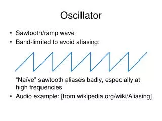
Local Oscillator distribution over fibre. Roshene McCool SPDO – Signal Transport & Networks. Contents. Distribution of LO signals over fibre Merlin L-Band Link (LBL) L-Band Link over fibre Results of experiments Is round trip correction required? Interferometry using a fibre LBL Results

E N D
Local Oscillator distribution over fibre Roshene McCool SPDO – Signal Transport & Networks
Contents • Distribution of LO signals over fibre • Merlin L-Band Link (LBL) • L-Band Link over fibre • Results of experiments • Is round trip correction required? • Interferometry using a fibre LBL • Results • Conclusions
Transfer of Local Oscillator Signals Over Fibre • Motivation • Accurate timing signals to all antenna & data processing stations • Like to have transmission over fibre to avoid RFI • Specifications • Not specified directly, yet… • Working to ±1 ps in 1 second (driven by astronomy at high frequencies) and ±10 ps over 10 minutes • Other LO over fibre systems • EVLA, 22 km • ATCA, 4.5 km • LO over fibre for the SKA & e-MERLIN • Same specifications, similar distances • e-MERLIN, 400km (120km longest unrepeatered hop) • Adapted MERLIN LO distribution equipment for optical transmission
Merlin L-Band Link (LBL) 1486.3 MHz signal arrives at the antenna with delay Φone way Good quartz oscillator locks a 10 MHz local oscillator signal using the incoming 1486.3 MHz Φround trip /2 = Φone way The LBL equipment switches to transmit At Jodrell the phase Φround trip of the incoming 1486.3 MHz signal is measured.
Phase stability of an LBL over fibre link ᶲround trip /2 - ᶲone way Back to Back 28.6 km @ 1550 nm 28.6 km @ 1310 nm 110 km no thermal control 110 km thermal control
Phase stability of an LBL over fibre link Back to Back 28.6 km @ 1550 nm 28.6 km @ 1310 nm 110 km no thermal control 110 km thermal control
Phase stability of an LBL over fibre link Back to Back 28.6 km @ 1550 nm 28.6 km @ 1310 nm 110 km no thermal control 110 km thermal control
Phase stability of an LBL over fibre link 1 ps r.m.s stability in 1 second, 2 ps r.m.s stability in 10 minutes 5 ps r.m.s stability in 3 hours. Back to Back 28.6 km @ 1550 nm 28.6 km @ 1310 nm 110 km no thermal control 110 km thermal control
Do we need round trip correction? Why not use a directly transmitted frequency standard?
Interferometry with a fibre LBL Observations of calibrator sources at 5 GHz Used a fibre LBL, distributing LO signals from Jodrell Bank to Pickmere (28.6 km) Other telescopes remained on a microwave LBL Direct comparison of competing architectures impossible – only 1 LO connections per antenna!! Observations were successful. Fibre LBL results impressive
Astronomy Phase at 5 GHz (correlated and round trip correction added) Using a microwave LBL Using a fibre LBL ** These plots are not direct comparisons and are made, using the same baseline (Knockin – Pickmere) over 5 hrs at different dates. Changes in Atmosphere will effect phase stability. However, we can certainly conclude the fibre LBL system is no worse than the microwave system.
Conclusions • LO distribution over fibre is possible • Over short links it may be possible to distribute phase with no round trip correction. • Hostage to external temperature changes • Distribution over long links is possible using thermally controlled lasers • Interferometry, performed at 5 GHz, using a fibre distributed LO was successful • Further work will address fibre distributed LOs over longer distances, using repeatered and optically amplified links
Wide area data networks Roshene McCool SPDO – Signal Transport and Networks
Contents • Defining the problem • Identifying the risks • How to approach it • Questions
Introduction • Defining the problem • 6.5 Peta bits per second total data transport requirements • In one day SKA will transport 35,000x total internet traffic of the USA* !! • Network along arms of 3,000 km length • To a network of ~ 300 AA stations & 600 dishes * AT&T Analyst Conference 2007 - Stankey x3 !
Technology risks • Technology risk in wide area networks – relatively low • 40 Gbps DPQSK systems • 10 GE SFP+ and XFP transponders commodity & address even long links • optical transmission mature technology - EDFAs, DCMs, DWDM, CWDM • Many possible suppliers • Long distance fibre networks (> 500 km) • Cost of high bit rates over long distance • Use commercial systems to avoid re-gen at lengths > 480 km • Availability of commercial dark fibre over long distances • Interfaces (may be none standard)
Risks • Radio Antenna environment • RFI requirements • Space • Supply • Continuity of supply • Turning hand-crafted designs into units for efficient manufacture, installation & operation. • Power • V. Hungry in many implementations
Risks related to scale Cost !!
How do we approach this problem ? • Use industry & obtain a turn key solution • Transfer risk from the project to the supplier • Now we can all go home! • This option doesn’t let us off the hook! • Have to produce a contract that will deliver for the SKA • Don’t know what it will cost • Evaluate ability of suppliers to deliver • Need a Plan B
How do we approach this problem ? • Target development of subsystems to directly address SKA digital signal processing design block • Efficient use of development resource • address interface issues • power • Identify cost effective solutions
How do we approach this problem ? • Critical Analysis of solutions • Technical risk is low, telecoms industry & pathfinders can provide solutions – but this can encourage complacency • Implementation is on a scale not yet conceived in industry • Hand-crafted designs in pathfinders do not necessarily scale either • Ask questions, build systems that lead to objective metrics upon which to base costed designs for implementation. • Optimisation is required to reduce costs