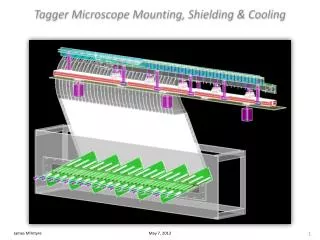
Tagger Microscope Mounting, Shielding & Cooling
Tagger Microscope Mounting, Shielding & Cooling. James M c Intyre. May 7, 2013. Mounting the Upper Enclosure. Mounting the Upper Enclosure. The prototype used a c-bracket affixed to a bolt threaded into a cylinder which is attached to a step motor.

Tagger Microscope Mounting, Shielding & Cooling
E N D
Presentation Transcript
Tagger Microscope Mounting, Shielding & Cooling James McIntyre May 7, 2013
Mounting the Upper Enclosure • The prototype used a c-bracket affixed to a bolt threaded into a cylinder which is attached to a step motor. • The parallel rail system will be mounted to the bottom-plate of the upper enclosure. • The motors are no longer attached to the bottom-plate. • The connections between the motors and upper enclosure bottom-plate (e.g. ball & joint fitting) will serve as the UConn / JLab interface point.
Mounting the Upper Enclosure • Possible locations to mount a marked plate for use by the survey team during installation and alignment.
Mounting the Upper Enclosure XXXXX XXXX
Mounting the Upper Enclosure Concept Drawing Only
Shielding the Lower (Electronics) Enclosure • The light guides enter the lower enclosure in sheets 15 fibers deep for each preamplifier board. • There is a gap of ~ 1.25 inches between each sheet of fibers. Need penetrations for cooling water loop & cables.
Lower (Electronics) Enclosure Cooling • Looking to remove 60 – 100 Watts. • Use of chilled water (possible chiller unit may be required). • Additional fans mounted in the enclosure to provide adequate air flow. • Also need similar system for between the shielding and the exterior of the lower enclosure. Enclosure Cooling Unit (Concept) Mounted on the side wall
Additional Drawings • Tagger Microscope Technical Drawings • http://zeus.phys.uconn.edu/wiki/index.php/Full_Scale_Tagger_Microscope_Drawings • UConn Student Projects in Nuclear Physics • http://zeus.phys.uconn.edu/wiki/index.php/Student_Projects_in_Nuclear_Physics