
Sensors
E N D
Presentation Transcript
What is a Flowchart? Flow charts are diagrams that show a particular process from beginning to end. They are used by programmers to help build logical paths for robots/computers to follow, and also by businesses to help solve problems and improve efficiency. Flow charts can be used to provide a visual aid when describing any type of process.
Problem Solving Flowchart You fool! You poor fool!
Imagine flowcharting your day… According to studies, the average human makes about 612 decisions a day. This equals to 4,900 decisions in a week and 254,800 in a year.
Rounded Box • This is used to represent an event which occurs automatically. Such an event will trigger a subsequent action, for example `receive telephone call’, or describe a new state of affairs. • There must be a START and an END box. All flow paths should be between these. • Start has 1 output and no inputs. • End box has no outputs and 1 input. END START Alarm goes off
Diamond Alarm goes off Used to represent a decision point in the process. Typically, the statement in the symbol will require a `yes’ or `no’ response and branch to different parts of the flowchart accordingly. Yes No END START Hit the Snooze button?
Rectangle Alarm goes off This is used to represent an event which is controlled within the process. Typically this will be a step or action which is taken. Go back to sleep Yes No END START Get out of bed Hit the Snooze button?
Linear Flowchart START Get a Pot Fill it most of the way with water Put it on the stove When boiling, add pasta Wait for the water to boil Turn on the burner Cook for 11 minutes, stirring occasionally Strain pasta from water. Put pasta on a plate. Get a Strainer ENJOY YOUR PASTA. END
Non-Linear Flowchart START Get a Pot Fill it most of the way with water Put it on the stove YES YES Wait for the water to boil Turn on the burner NO Add pasta NO Cook for 11 minutes, stirring occasionally Strain pasta from water. Put pasta on a plate. Get a Strainer ENJOY YOUR PASTA THROW OUT THE PASTA AND ORDER A PIZZA Do you like pasta? Is the water boiling? Why did you make pasta then?
Flowchart Basics START INPUT SEQUENTIAL NO DECISION YES OUTPUT END
Brick Parts -Sides Computer Connection OUTPUT PORTS (Motors) B & C - Large Motors D - Small Motor INPUT PORTS (Sensors) 1 2 3 4 PC D C B A USB PORT SD CARD SLOT SPEAKER The best use of sensors is with the Switch Flow Control block
SWITCH If the color sensor reads a blue color, then it will say “Blue”. If the color sensor does not read a blue color, then it will say “LEGO”. Switches are used, primarily with sensors, to help a robot interact with its environment and make decisions. When the appropriate conditions are met, the robot will run the program in the CHECK box. If the appropriate conditions are not met, the robot will run the program in the X box. If, then statements…
LOOP Loops are usedto repeat certain commands a definite or infinite amount of time depending on the setting. This can help save time and space in the program. In the program below, the robot will drive forward for 3 seconds at 50% power, then turn right at 30% power for 1 rotation. This will repeat for 4 times.
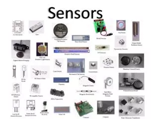
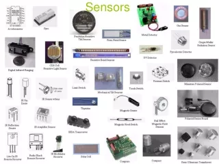
Sensors Color / Light Sensor Gyroscopic Sensor Touch Sensor Ultrasonic Sensor Sensors are used by robots to interact with its environment The best use of sensors is with the Switch Flow Control block
Sensors Color / Light Sensor Gyroscopic Sensor Touch Sensor Ultrasonic Sensor
Touch Sensor When the Touch Sensor is activated, it closes an electrical circuit which allows current to flow. If the sensor is released the circuit is broken and no current flows. The flow or lack of current is detected by the brick allowing it to know whether the sensor is pressed or not. • The sensor has three modes: • pressed and held • pressed and released • released
ULTRASONIC SENSOR PORT VIEW • Sends an ultrasonic (rapid sound) signal out and receives back their echoes to help the robot determine the distance of objects. • Can measure distance in centimeters or inches. • Features • Distances measured up to 250 cm (~100-inch) • Accuracy of +/- 1 cm (+/- 0.4-inch) • Has the ability to recognize other ultrasonic sound (other robots)
ULTRASONIC SENSOR EV3 OBJECT
ULTRASONIC SENSOR PORT VIEW • The Ultrasonic Sensor uses the speed that sound waves travel (341 m/s) to measure distance to an object. • The sensor has two openings; • one opening emits ultrasonic waves, • the other opening receives them. • The sensor measures the distance by timing how long it takes for an ultrasonic wave sent out by the emitter to bounce off an object and come back to the receiver. (Time Wave is Emitted) x(Speed of Sound) 2* Distance to Object = *Wave has to travel to object and back.
Gyro Sensor Used as assistance in stability of a robot. The mechanical system can determine the rotation and robot orientation on several axes giving the possibility for users to measure the angles and design robots with proper navigation systems. Students can use this sensor in building balancing robots with high accuracy in movements. Similar to the technology that keeps the image on smartphones orientated in the correct direction.
Color Sensor • Used for object detection, follow a line, sorting objects, or detection of a normal or reflected light. • The digital EV3 Color Sensor could be used for applications to detect • the absence of color, • the difference between colors, • up to seven different colors, • the light intensity. • Features • detection for up to seven colors; • detect the absence of color; • it works in ambient light; • sample rate of 1 kHz; • Auto-ID is built into the EV3 Software;
How do our eyes see color? GREEN!
LIGHT REFLECTION SENSOR BLACK PURPLE BLUE GREEN YELLOW ORANGE RED WHITE Measures the percentage of light reflected off of a surface. Brighter surface colors (white, yellow) reflect a larger percentage of light back to the sensor. (80 - 90%) Darker surface colors (black, blue) reflect a lower percentage of light back to the sensor (10 - 20%)
PORT VIEW Port View Motor Control IR Control Brick Program Brick Dialog Allows you to instantaneously see the status or reading of the motors and sensors plugged into the brick.
Port View Motor Control IR Control Brick Program Brick Dialog PORT VIEW Port View Port View Motor Control IR Control Brick Program Brick Dialog Allows you to instantaneously see the status or reading of the motors and sensors plugged into the brick.
EV3 --- --- --- --- 2: GYRO-ANG 78 deg --- --- --- PORT VIEW --- --- 24 6 Motors 4:US-DIST-CM 79 --- -15 143.5 CM 2 45 Sensors Allows you to instantaneously see the status or reading of the motors and sensors plugged into the brick.
ULTRASONIC SENSOR PORT VIEW EV3 --- --- --- --- --- --- --- --- OBJECT 4:US-DIST-CM 4:US-DIST-CM 255.0 CM --- --- --- --- --- --- 85.2 140.3 143.5 126.5 113.4 132.9 98.5 73.6 66.7 CM 2 45
ULTRASONIC SENSOR PORT VIEW EV3 --- --- --- --- --- --- --- --- OBJECT 4:US-DIST-CM 4:US-DIST-CM 255.0 CM --- --- --- --- --- --- 85.2 140.3 143.5 126.5 113.4 132.9 98.5 73.6 66.7 CM 2 45
GYROSCOPIC SENSOR --- --- --- --- 2: GYRO-ANG deg --- --- --- 33 25 27 0 47 41 39 -42 -26 -15 0 2 45 The digital EV3 Gyro Sensor measures the robot’s rotational motion and changes in its orientation. Used to create precise turns measure angles, create balancing robots. Angle mode measures angles with an accuracy of +/- 3 degrees Gyro mode has a maximum output of 440 degrees/second
LIGHT REFLECTION SENSOR --- --- --- --- 4:US-DIST-CM --- --- --- 79 23 29 12 94 17 69 81 86 PCT BLACK PURPLE BLUE GREEN YELLOW ORANGE RED WHITE