Download
1 / 6
60 likes | 210 Views
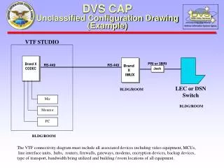
Jack. DVS CAP Secure Configuration Drawing (Example) (Replace this header with your Site ID). NOTE: This Configuration is only authorized with proper isolation integrated within the A/B Switch, such as optical isolation. (See the current list on the Approved Equipment page.). BLDG/ROOM.

E N D
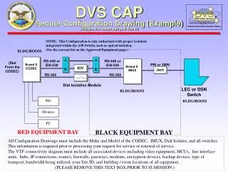
Jack DVS CAP Secure Configuration Drawing (Example) (Replace this header with your Site ID) NOTE: This Configuration is only authorized with proper isolation integrated within the A/B Switch, such as optical isolation. (See the current list on the Approved Equipment page.) BLDG/ROOM Brand X CODEC A / B A / B RS-449 or EIA-530 RS-449 or EIA-530 Brand X IMUX (Dial From the CODEC) PRI or 3BRI KIV RS-366 RS-366 Dial Isolation Module LEC or DSN Switch BLDG/ROOM Mic BLDG/ROOM Monitor PC RED EQUIPMENT BAY BLACK EQUIPMENT BAY All Configuration Drawings must include the Make and Model of the CODEC, IMUX, Dial Isolator, and all switches. This information is required prior to processing your request for service or renewal of service. The VTF connectivity diagram must include all associated devices including video equipment, MCUs, line interface units, hubs, IP connections, routers, firewalls, gateways, modems, encryption devices, backup devices, type of transport, bandwidth being utilized, your Site ID, and building / room locations of all equipment. (PLEASE REMOVE THIS TEXT BOX PRIOR TO SUMISSION.)
Jack DVS CAP Secure Configuration Drawing (Example) (Replace this header with your Site ID) NOTE: This Configuration is only authorized with proper isolation integrated within the A/B Switch, such as optical isolation. (See the current list on the Approved Equipment page.) BLDG/ROOM Brand X CODEC RS-449 or EIA-530 A / B A / B RS-449 or EIA-530 Brand X IMUX PRI or 3BRI KIV-7 (Dial ONLY From the IMUX) LEC or DSN Switch BLDG/ROOM Mic BLDG/ROOM Monitor PC BLACK EQUIPMENT BAY RED EQUIPMENT BAY All Configuration Drawings must include the Make and Model of the CODEC, IMUX, Dial Isolator, and all switches. This information is required prior to processing your request for service or renewal of service. The VTF connectivity diagram must include all associated devices including video equipment, MCUs, line interface units, hubs, IP connections, routers, firewalls, gateways, modems, encryption devices, backup devices, type of transport, bandwidth being utilized, your Site ID, and building / room locations of all equipment. (PLEASE REMOVE THIS TEXT BOX PRIOR TO SUMISSION.)
Jack DVS CAP Secure Configuration Drawing (Example) (Replace this header with your Site ID) UNCLASS PATH F / M F / M (Fiber Modem*) (Fiber Modem*) BLDG/ROOM Brand X CODEC A / B A / B RS-449 or EIA-530 RS-449 or EIA-530 Brand X IMUX (Dial From the CODEC) PRI or 3BRI KIV (KIV-7,or KIV-19) RS-366 RS-366 LEC or DSN Switch Dial Isolation Module BLDG/ROOM Mic BLDG/ROOM Monitor *Fiber Modems Must Extend RS-449 or EIA-530 Handshaking Signals in Addition to Data PC BLACK EQUIPMENT BAY RED EQUIPMENT BAY All Configuration Drawings must include the Make and Model of the CODEC, IMUX, Dial Isolator, and all switches. This information is required prior to processing your request for service or renewal of service. The VTF connectivity diagram must include all associated devices including video equipment, MCUs, line interface units, hubs, IP connections, routers, firewalls, gateways, modems, encryption devices, backup devices, type of transport, bandwidth being utilized, your Site ID, and building / room locations of all equipment. (PLEASE REMOVE THIS TEXT BOX PRIOR TO SUMISSION.)
Jack DVS CAP Secure Configuration Drawing (Example) (Replace this header with your Site ID) (Patch KIV-7 into path for Classified – remove/replace with UNCLASS patch for Unclassified.) BLDG/ROOM Brand X CODEC RS-449 or EIA-530 P / P P / P RS-449 or EIA-530 Brand X IMUX PRI or 3BRI KIV-7 (Patch Panel) (Patch Panel) LEC or DSN Switch Dial From IMUX BLDG/ROOM Mic BLDG/ROOM Monitor PC BLACK EQUIPMENT BAY RED EQUIPMENT BAY All Configuration Drawings must include the Make and Model of the CODEC, IMUX, Dial Isolator, and all switches. This information is required prior to processing your request for service or renewal of service. The VTF connectivity diagram must include all associated devices including video equipment, MCUs, line interface units, hubs, IP connections, routers, firewalls, gateways, modems, encryption devices, backup devices, type of transport, bandwidth being utilized, your Site ID, and building / room locations of all equipment. (PLEASE REMOVE THIS TEXT BOX PRIOR TO SUMISSION.)
Jack DVS CAP Secure Configuration Drawing (Example) (Replace this header with your Site ID) (Patch KIV-7 into path for Classified -/- Remove/replace with UNCLASS patch for Unclassified.) BLDG/ROOM (Patch Panel) (Patch Panel) Brand X CODEC RS-449 or EIA-530 P / P P / P RS-449 or EIA-530 Brand X IMUX (Dial From the CODEC) PRI or 3BRI KIV RS-366 RS-366 Dial Isolation Module LEC or DSN Switch BLDG/ROOM Mic BLDG/ROOM Monitor PC RED EQUIPMENT BAY BLACK EQUIPMENT BAY All Configuration Drawings must include the Make and Model of the CODEC, IMUX, Dial Isolator, and all switches. This information is required prior to processing your request for service or renewal of service. The VTF connectivity diagram must include all associated devices including video equipment, MCUs, line interface units, hubs, IP connections, routers, firewalls, gateways, modems, encryption devices, backup devices, type of transport, bandwidth being utilized, your Site ID, and building / room locations of all equipment. (PLEASE REMOVE THIS TEXT BOX PRIOR TO SUMISSION.)
Jack DVS CAP Secure Configuration Drawing (Example) (Replace this header with your Site ID) (Fiber Modem*) F / M F / M (Fiber Modem*) (Patch KIV-7 into path for Classified -/- Remove/replace with UNCLASS patch for Unclassified.) BLDG/ROOM Brand X CODEC RS-449 or EIA-530 P / P P / P RS-449 or EIA-530 Brand X IMUX (Dial From the CODEC) PRI or 3BRI KIV (Patch Panel) (Patch Panel) RS-366 RS-366 Dial Isolation Module LEC or DSN Switch BLDG/ROOM Mic BLDG/ROOM Monitor PC BLACK EQUIPMENT BAY RED EQUIPMENT BAY All Configuration Drawings must include the Make and Model of the CODEC, IMUX, Dial Isolator, and all switches. This information is required prior to processing your request for service or renewal of service. The VTF connectivity diagram must include all associated devices including video equipment, MCUs, line interface units, hubs, IP connections, routers, firewalls, gateways, modems, encryption devices, backup devices, type of transport, bandwidth being utilized, your Site ID, and building / room locations of all equipment. (PLEASE REMOVE THIS TEXT BOX PRIOR TO SUMISSION.)