Download
1 / 14
140 likes | 225 Views
Explore the impact and potential improvements of LHCb trigger systems for CP violation studies in B-meson decays. Learn about trigger stages, preselection criteria, secondary vertex reconstruction, data cuts, and analysis results to enhance event selection efficiency.

E N D
Efficiency of LHCb Trigger Systems Elizabeth Leicht Supervisor: Frederic Teubert Experiment: LHCb
The LHCb and CP Violation • CP violation was originally in neutral kaon decays in 1964. • However, in the B-meson system there are many more decay modes available than for neutral kaon decay. • When complete the LHC will be the largest source of B mesons of all accelerators, therefore, the LHCb detector is designed to exploit this large source of b-hadrons.
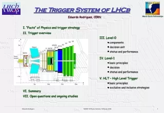
A Brief Review of the Trigger System • A trigger system is the gatekeeper of the experiment. It determines which data will be saved for later analysis and which will be thrown away. • For the LHCb experiment, only the first two trigger levels have been implemented at this time. • L0 is a fast, but crude trigger that is implemented using hardware and data from only a few detectors. • L1 the first software trigger and is a series of algorithms. It utilizes more data than L0 and is of course slower.
Preselection Criteria • The impact parameter (d0)with respect to the primary vertex must have a value of less than 5 mm. • The associated error of the impact parameter (d)must be be less than 500 m. • The normalized impact parameter (d0/ d ) must be greater than 1. Primary Vertex Track Impact parameter with respect to the primary vertex
Reconstructing the Secondary Vertex Positively Charged Track • A loop is made over all of the tracks passing the preselection criteria, to separate the tracks by charge. • The next step is to run through all possible combinations of oppositely charged tracks and reconstruct secondary vertices. Primary Vertex Negatively Charged Track Reconstructed Secondary Vertex
Data Cuts Made from Reconstructed Secondary Vertex • A vertex separation cut. The distance between the primary and the reconstructed secondary vertices must be greater than 0.5 mm. • A 2 cut. The value of 2 must be less then 5. A Little More About 2 Track 1 Not exactly an intersection in three dimensional space. Closest approach between the two tracks. Track 2
More Data Cuts Made from Reconstructed Secondary Vertex • An invariant mass cut. The combined invariant mass of the two candidate tracks must fall between 5.0 GeV. and 5.5 GeV. • The significance of impact parameter, d0/ d, for both candidate pions must be greater than 3. • The momentum vector of the reconstructed B must be consistent with the flight path from the primary to the secondary vertex, such that cosB> 0.95 , where B> is the opening angle between these two vectors. Secondary Vertex B Primary Vertex
Last of the Data Cuts for the Reconstructed Secondary Vertex • The transverse momentum, of both pions must exceed 1 GeV/c and at least one pion must have a transverse momentum of greater than 3.5 GeV/c. • For the reconstructed B, the transverse momentum must exceed 3 GeV/c. Transverse Momentum: PT = P•sin where is the angle between the P vector and a unit vector in the z direction.
Some Results Plot of the Combined Invariant Mass Values Number of Events Selected Combined Invariant Mass (MeV/c2)
Plot of the Combined Invariant Mass Values with L0 and L1 Triggers Number of Events Selected Combined Invariant Mass (MeV/c2)
Conclusions • From the analysis I’ve done it appears that the L1 trigger is selecting the desired events with high efficiency. • The issue is the L0 trigger. • One culprit for the low L0 efficiency may be the impact parameter. • It may be possible to make the cut of the L1 trigger harder, therefore, suppressing more background, while retaining high efficiency.
Thanks To: • The University of Michigan • Dr. Krisch, Dr. Neil, & Dr. Dershem • Frederic Teubert & Thomas Schietinger • The NSF • CERN • My fellow REU students.