Download
1 / 30
300 likes | 417 Views
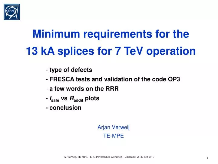
Arjan Verweij TE-MPE. Minimum requirements for the 13 kA splices for 7 TeV operation. type of defects - FRESCA tests and validation of the code QP3 a few words on the RRR - I safe vs R addit plots - conclusion.

E N D
Arjan VerweijTE-MPE Minimum requirements for the 13 kA splices for 7 TeV operation • type of defects- FRESCA tests and validation of the code QP3 • a few words on the RRR- Isafe vs Raddit plots- conclusion A. Verweij, TE-MPE. LHC Performance Workshop – Chamonix 25-29 Feb 2010
Defect A is very likely to be found using the monitoring feature of the nQDS system, which should reveal all bad splices with a resistance larger than a few nW. Additionally, the sub mV detection threshold on the bus segments will trigger before the resistive dissipation will cause the SC-to-normal transition followed by a thermal runaway. Defect A is mechanically weak (even if it has a resistance of a few nW), and running the machine with such a defect presents a serious risk!!! A. Verweij, TE-MPE. LHC Performance Workshop – Chamonix 25-29 Feb 2010
Defects B, C, and D can be present on 1 or 2 sides of the joint. • Single sided defects B and C are the worst case scenarios, assuming that the defect size is estimated from a R16 measurement or from a Rsegment measurement (30-100 m long). These defects have been used in the FRESCA tests. • Defect D is the predominant defect in the machine. The stabiliser-stabiliser contact in the vertical gaps may degrade in time (see lateron). • Maximum safe operating currents are given for single-sided defect B (or C) as a function of the additional resistance Raddit (at 300 K), with Raddit=R16,defect-R16,good. A. Verweij, TE-MPE. LHC Performance Workshop – Chamonix 25-29 Feb 2010
FRESCA tests and validation of the code QP3 Thanks to: G. Willering, G. Peiro, D. Richter, H. Prin, C. Urpin, P. Fessia, Th. Renaglia, Ch. Scheuerlein, L. Gaborit, L. Bottura, K. Chaouki, L. Gaborit, L. Fiscarelli, V. Inglese, G. Montenero, C. Petrone, R. Principe, S. Triquet for sample preparation, instrumentation, data acquisition, and running of the test station and cryogenics. Thanks to: R. Berkelaar and M. Casali for comparison of QP3 with two other models for a specific case study. A. Verweij, TE-MPE. LHC Performance Workshop – Chamonix 25-29 Feb 2010
Experiments in FRESCA (B-163) are performed, mainly to validate the calculation code. Up to now 3 samples with ‘on-purposely-built-in’ defects are measured. Two more samples will be measured in Feb. 2010. Step 1: Sample definition Determine values for Raddit, RRRcable, RRRbus, RRRjoint, and geometry (type of insulation, positioning of heaters, spiders, spacers etc.) Step 2: Measurements Measure the thermal runaway time tTR for various currents, temperatures, and fields. During each test the voltage and temperatures are recorded. The power converter is switched off before the defective joint reaches 300 K. Step 3: Analysis Fine-tune the effective cooling through the bus insulation and the joint insulation, so that the calculated tTR(I, B=0, T=1.9 K) curve and calculated V(t) curves are in good agreement with the measurements. Thevalidated code is then used to calculate Isafe(Raddit) for the machine, assuming the worst heat transfer observed on the samples, and the worst RRR values that can occur in the machine. A. Verweij, TE-MPE. LHC Performance Workshop – Chamonix 25-29 Feb 2010
A. Verweij, TE-MPE. LHC Performance Workshop – Chamonix 25-29 Feb 2010
Sample pictures Sample 1 (61 mW) Sample 3A left (26 mW) Sample 2A left (32 mW) Sample 3A right (43 mW) Sample 2A right (43 mW) Sample 3B (21 mW) Pictures by J.-M. Dalin Sample 2B (42 mW) A. Verweij, TE-MPE. LHC Performance Workshop – Chamonix 25-29 Feb 2010
Typical test run with and without thermal runaway Measure tTR(T,I,B) Switch off current if V>Vthr (100-150 mV) Current between 2-20 kA 1-3 s Rapidly increasing U and T (heating>>>cooling) Ramp up current <100 ms Create a normal zone in the NSBC by firing the heaters Increasing U and T (heating>cooling) Stable U and T (heating = cooling) Time tTR (typically 2-50 s) A. Verweij, TE-MPE. LHC Performance Workshop – Chamonix 25-29 Feb 2010
Typical correlation experimental and calculated V(t) curves run 090813.21 Heat pulse tTR =15.2 s A. Verweij, TE-MPE. LHC Performance Workshop – Chamonix 25-29 Feb 2010
Correlation experimental and calculated tTR(I) curves. For each sample the effective heat transfer to the helium is individually fitted 32+43 mW 61 mW 42 mW Cooling to He gives about 1-2 kA improvement A. Verweij, TE-MPE. LHC Performance Workshop – Chamonix 25-29 Feb 2010
Applying the ‘best fit’ heat transfer values for a large and a small defect under ‘machine conditions’ Conclusion: Although the difference in effective heat transfer is a factor 2, the resulting error in Isafe is about ±0.5 kA (at high currents). The error might be a bit larger for the RB circuit due to the longer decay time constant. Used for Isafe(Raddit) plots for the machine A. Verweij, TE-MPE. LHC Performance Workshop – Chamonix 25-29 Feb 2010
A few words on: • RRRcable • RRRbus • RRRU-profile and RRRwedge Data coming from: F. Bertinelli, A. Bonasia, Z. Charifoulline, P. Fessia, B. Flora, S. Heck, M. Koratzinos, D. Richter, C. Scheuerlein, G. Willering A. Verweij, TE-MPE. LHC Performance Workshop – Chamonix 25-29 Feb 2010
RRRcable • RRR of the virgin cable (i.e. after production) is 70-100. • Data from FRESCA tests show RRR of 100, 130, 160 and 180. • RRR increases to about 130 and 200 when the cable is heated during 4 minutes to 222 C (SnAg melting temperature) and 270 C (nominal soldering peak temperature) respectively (using 100 C/min). • Conclusion: • The RRR of the cable is probably >150 in a well-soldered joint. However, in a defective joint, especially of types A and C, the cable has probably not been subject to a high temperature (>200 C) and the RRR enhancement due to the soldering process is small. For simulations I will assume RRRcable=80. A. Verweij, TE-MPE. LHC Performance Workshop – Chamonix 25-29 Feb 2010
RRRbus • ← • Biddle data in many segments of the machine show large spread in RRR from 50-400 (measurements: MPE-CP, analysis: M. Koratzinos). • Biddle data are unreliable in the measured range (10-20 mV) • (Task Force LHC splices consolidation, 17/12/2009). • Few Keithley data from sector L2 show RRR of 200-300. • There is no evidence that different sectors contain copper from different production batches. • Data from FRESCA tests show RRR>250. • Data from on 4 RB and 4 RQ bus samples show RRR of 220-300. Conclusion: I will use RRR of 100 and 160. Better measurements in the machine using the nQPS boards in stead of the Biddle may give a more realistic RRR value. A. Verweij, TE-MPE. LHC Performance Workshop – Chamonix 25-29 Feb 2010
RRRU-piece and RRRwedge • All U-pieces used before 2009 are produced by hot extrusion. • RRR measurements on 8 U-profiles from several sectors in the machine show RRR of 250-300. • The RRR of the U-pieces of the 2009 production (machined from OFE Cu sheet) and the RRR of all wedges have a lower RRR of about 130, as deduced from the correlation between the ‘Vickers hardness’ and the RRR. For simulations I will use RRRU_piece=RRRwedge=RRRbus (so also 100 and 160). A. Verweij, TE-MPE. LHC Performance Workshop – Chamonix 25-29 Feb 2010
Isafe vs Raddit plots • The currents in the following plots are calculated for: • RRRcable=80, • RRRbus=RRRwedge=RRRU-profile=100 and 160, • Tprop=10 and 20 s • Worst heat transfer coefficient as deduced from the 3 FRESCA samples • No additional safety margin is added!! A. Verweij, TE-MPE. LHC Performance Workshop – Chamonix 25-29 Feb 2010
Quench scenarios • Quenches in LHe: • Quench due to mechanical movement of the Non-Stabilised Bus Cable. Not very likely below 7 kA (because all sectors already powered up to 7 kA). • Quench due to global beam losses. • Quench due to normal zone propagation through the bus from an adjacent quenching magnet. Not possible below 6 kA (RQ) and 8 kA (RB) respectively. • Quenches in GHe: • Quench due to warm helium from adjacent quenching magnet. Very unlikely below about 5 kA, almost certain above 9 kA. Time between quench of magnet and quench of interconnect depends mainly on: • current, • number of magnets that are quenching, • position in the cryogenic cell. • For the calculations I will assume no cooling to helium and a propagation time of: • 10 s for high current quenches (I>11 kA), • 20 s for intermediate currents (7-9 kA). A. Verweij, TE-MPE. LHC Performance Workshop – Chamonix 25-29 Feb 2010
Quenches in GHe A. Verweij, TE-MPE. LHC Performance Workshop – Chamonix 25-29 Feb 2010
RB in LHe RRRbus from 100 to 160: DI=8%, DR=5 mW Note the large improvement due to the cooling to He A. Verweij, TE-MPE. LHC Performance Workshop – Chamonix 25-29 Feb 2010
RQ in LHe RRRbus from 100 to 160: DI=7%, DR=5 mW A. Verweij, TE-MPE. LHC Performance Workshop – Chamonix 25-29 Feb 2010
RB in GHe A. Verweij, TE-MPE. LHC Performance Workshop – Chamonix 25-29 Feb 2010
RQ in GHe A. Verweij, TE-MPE. LHC Performance Workshop – Chamonix 25-29 Feb 2010
13 kA requirements Conclusion:Raddit,RB<11 mW and Raddit,RQ<15 mW are required for operation around 7 TeV. Better knowledge of RRRbus will hardly increase these numbers A. Verweij, TE-MPE. LHC Performance Workshop – Chamonix 25-29 Feb 2010
5 TeV requirements Remark: better knowledge of RRRbus may give another 10 mW margin. A. Verweij, TE-MPE. LHC Performance Workshop – Chamonix 25-29 Feb 2010
3.5 TeV requirements A. Verweij, TE-MPE. LHC Performance Workshop – Chamonix 25-29 Feb 2010
Raddit=RNSBC ║ RCu-Cu • In case of a quench the current will flow partially through the copper of the cable, and partially through the Cu-Cu contact between the bus stabiliser and the joint stabiliser. • We know that many joints have a non-stabilised bus cable with a length of at least 15 mm (so RNSBC>20 mW). • The Cu-Cu contacts might degrade in time, due to electromagnetic and thermal cycling, and possibly due to thermal and pressure shocks during a quench. So: Raddit may increase and hence Isafe decrease. • Furthermore, if RCu-Cu is small as compared to RNSBC and if RRRCu-Cu<<RRRNSBC then the room temperature measurement of Raddit could give a somewhat underestimated Raddit at cold and hence an overestimated value of Isafe. A. Verweij, TE-MPE. LHC Performance Workshop – Chamonix 25-29 Feb 2010
Safe running at 13 kA • Safe 13 kA operation requires Raddit,RB<11 mW and Raddit,RQ<14 mW. Proper quench protection is usually based on an adiabatic approach which further decreases the maximum Raddit to 8 and 13 mW. One can be sure that there are many hundreds of defects with larger Raddit in the machine. Better know-how of the RRRbus might increase the maximum Raddit a bit, but they will stay well below 20 mW. • ‘Segment’ measurements at warm (or any other temperature) are not accurate enough to detect these small values. • “High current pulsing” seems no option given the large number of defects, but might eventually be useful for a final in-situ qualification test of the circuits. • Raddit may degrade during the lifetime of the LHC. • Especially for small resistances, the measured Raddit(300 K) may not be representative for Raddit(10 K). ! Conclusion: For safe running around 7 TeV, a shunt has to be added on all 13 kA joints, also on those with small Raddit. Joints with high Raddit or joints with large visual defects should be resoldered and shunted. A. Verweij, TE-MPE. LHC Performance Workshop – Chamonix 25-29 Feb 2010
For implementation see talk P. Fessia • Shunt requirements: • One shunt on each side of the joint or one shunt covering both sides • High RRR copper (>100). • Sufficiently large cross-section. • Short distance lwc. • Good electrical contact • between shunt and stabilisers. • Small forces acting on shunt • (so somewhat flexible shunt). • Large cooling surface. A. Verweij, TE-MPE. LHC Performance Workshop – Chamonix 25-29 Feb 2010
Conclusion ► The calculation code QP3 is validated. Different effective heat transfer to helium is needed per sample in order to have very good quantitative agreement. This difference has an error of about ±500 A on the safe current. ►Actual calculations of the safe current are based on conservative values for RRRcable and RRRbus. Better knowledge of RRRbus, by means of measurement in several sectors in the machine, is needed if one wants to push the energy from 3.5 TeV towards 5 TeV, but is of no real importance for operating at 7 TeV. ►For safe running around 7 TeV, a shunt has to be added on all 13 kA joints, also on those with small Raddit. Joints with high Raddit or joints with large visual defects should be resoldered and shunted. A Cu-shunt with high RRR and a cross-section of 16x2 mm2 is sufficient, if soldered at short distance from the gap. Experimental confirmation by means of a test in FRESCA should be foreseen. A. Verweij, TE-MPE. LHC Performance Workshop – Chamonix 25-29 Feb 2010
Disturbances causing a superconducting-to-normal transition in a 13 kA joint New QPS acts here Stable resistive heating Recovery Cooling>Heating Cooling>Heating Localised slow thermal runaway Non-localised slow thermal runaway Fast thermal runaway Good thermal and electrical contacts. No propagation to bus. Good thermal and electrical contacts. Propagation to bus. Bad thermal and electrical contacts A. Verweij, TE-MPE. LHC Performance Workshop – Chamonix 25-29 Feb 2010