Download
1 / 67
680 likes | 841 Views
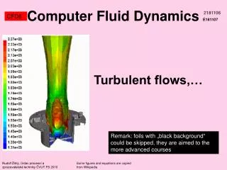
Computer Fluid Dynamics E181107. 2181106. CFD6. Turbulent flows,…. Remark : fo i l s with „ black background “ could be skipped, they are aimed to the more advanced courses. Rudolf Žitný, Ústav procesní a zpracovatelské techniky ČVUT FS 2010.

E N D
ComputerFluid DynamicsE181107 2181106 CFD6 Turbulent flows,… Remark: foils with „black background“ could be skipped, they are aimed to the more advanced courses Rudolf Žitný, Ústav procesní a zpracovatelské techniky ČVUT FS 2010 Some figures and equations are copied from Wikipedia
Turbulence CFD6 Source of nonlinearities of NS equations are inertial and viscous terms for incompressible fluids the equivalent conservative form The convection term is a quadratic function of velocities – source of nonlinearities and turbulent phenomena
Instabilities Rayleigh Benard convection Tu L >1100 Tb CFD6 Horizontal liquid layer heated from below is in still (viscous forces attenuate small disturbances) until the buoyancy exceeds a critical level RaL. Then the more or less regular cells with circulating fluid are formed. Even if the stability limit was exceeded the flow pattern is steady and remains laminar. At this stage the nonlinear convective term is not so important. Only if RaL>109 (approximately) eddies start to be chaotic, velocity fluctuates and the flow is turbulent.
Instabilities Karman vortex street CFD6 Repeating pattern of swirling vortices caused by the unsteady separation of flow of a fluid over bluff bodies. A vortex street will only be observed above a limiting Re value of about 90. L Even if the stability limit was exceeded the flow pattern is steady and remains laminar.
Distarbunce is attenuated Distarbunce is amplified Turbulence CFD6 Relative magnitude of inertial and viscous terms is Reynolds number Increasing Re increases nonlinearity of NS equations. This nonlinearity leads to sensitivity of NS solution to flow disturbances. Laminar flow: Re<Recrit Turbulent flow: Re>Recrit
Turbulence - fluctuations CFD6 Turbulence can be defined as a deterministic chaos. Velocity and pressure fields are NON-STATIONARY (du/dt is nonzero) even if flowrate and boundary conditions are constant. Trajectory of individual particles are extremely sensitive to initial conditions (even the particles that are very close at some moment diverge apart during time evolution). . Velocities, pressures, temperatures… are still solutions of NS and energy equations, however they are nonstationary and form chaotically oscillating vortices (eddies). Time and spatial profiles of transported properties are characterized by fluctuations Actual value at given time and space Mean value fluctuation
Turbulence - fluctuations CFD6 • Statistics of turbulent fluctuations • Mean values (remark: mean values of fluctuations are zero) • rms (root mean square) • Kinetic energy of turbulence • Intensity of turbulence • Reynolds stresses
E() Spectral energy of turbulent eddies =2f/u 1/L 1/ Turbulent eddies - scales CFD6 Kinetic energy of turbulent fluctuations is the sum of energies of turbulent eddies of different sizes Large energetic eddies (size L) break to smaller eddies. This transformation is not affected by viscosity Inertial subrange (inertial effects dominate and spectral energy depends only upon wavenumber and ) Smallest eddies (size is called Kolmogorov scale) disappear, because kinetic energy is converted to heat by friction wavenumber (1/size of eddy) Typical values of frequency f~10 kHz, Kolmogorov scale ~0.01 up to 0.1 mm Kolmogorov scale decreases with the increasing Re
Viscous subrange - scales CFD6 Kolmogorov scales (the smallest turbulent eddies) follow from dimensional analysis, assuming that averything depends only upon the kinematic viscosity and upon the rate of energy supply in the energetic cascade (only for small isotropic eddies, of course) velocity scale Time scale Length scale These expressions follow from dimension of viscosity [m2/s] and the rate of energy dissipation [m2/s3]
Viscous scale - tutorial CFD6 Derive time scale of the smallest turbulent eddies Time scale
Inertial subrange - scales CFD6 Spectral energy E decreases in the turbulent cascade when turbulent eddies are decomposed to smaller and smaller eddies. Energy transformation is not affected by viscosity in the inertial subrange Dimension analysis in the inertial subrange And this is the famous Kolmogorov’s law of 5/3
Turbulent eddies - scales CFD6 Wikipedia (abbreviated) Turbulent flow is composed by "eddies" of different sizes. The sizes define a characteristic length scale for the eddies, which are also characterized by velocity scales and time scales (turnover time) dependent on the length scale. The large eddies are unstable and break up originating smaller eddies, and the kinetic energy of the initial large eddy is divided into the smaller eddies that stemmed from it. The energy is passed down from the large scales of the motion to smaller scales until reaching a sufficiently small length scale such that the viscosity of the fluid can effectively dissipate the kinetic energy into internal energy. In his original theory of 1941, Kolmogorov postulated that for very high Reynolds number, the small scale turbulent motions are statistically isotropic. In general, the large scales of a flow are not isotropic, since they are determined by the particular geometrical features of the boundaries (the size characterizing the large scales will be denoted as L). Kolmogorov introduced a hypothesis: for very high Reynolds numbers the statistics of small scales are universally and uniquely determined by the kinematic viscosity () and the rate of energy dissipation (). With only these two parameters, the unique length that can be formed by dimensional analysis is
Turbulent eddies - scales CFD6 • Why and when it is important to know the turbulent scales: • Rate of chemical reactions depends upon the rate of micromixing determined by the frequency and the size of turbulent eddies • Breakup of droplets depends upon the energy and size of turbulent eddies (too large eddies only move but do not break a droplet) • Coalescence of bubbles depends upon collision frequency, collision speed, and these parameters are correlated with the energy dissipation rate and the length microscale l corresponding to radius of bubbles Ronnie Andersson and Bengt Andersson. Modeling the Breakup of Fluid Particles in Turbulent Flows. AIChE Journal June 2006 Vol. 52, No. 6 H. Venneker, Jos J. Derksen and Harrie E. A. Van den Akker. Population balance modeling of aerated stirred vessels based on CFD . AIChE J. Volume 48, Issue 4, April 2002, 673–685
L DNS Direct Numerical Simulation CFD6 In order to resolve all details of turbulent structures it is necessary to use mesh with grid size less than the size of the smallest (Kolmogorov) eddies. N-grid points in one direction should be (based upon dimensional ground) Velocity scale u in previous expression is related to magnitude of turbulent fluctuations (rms of u’, or k). The Re related to the velocity fluctuation is called turbulent Reynolds number. Table concerns DNS modelling of channel flow experiments (rewritten from Wilcox: Turbulence modelling, chapter 8). Remark: Re~106 or 107 at flow around a car or flow around wings
DNS Direct Numerical Simulation CFD6 Direct numerical simulation of transition and turbulence in compressible mixing layer FU Dexun , MA Yanwen ZHANG Linbo Vol 43 No.4, SCIENCE IN CHINA (Series A), April 2000 Abstract The three-dimensional compressible Navier-Stokes equations are approximated by a fifth order upwind compact and a sixth order symmetrical compact difference relations combined with threestage Runge-Kutta method. The computed results are presented for convective Mach number Mc = 0.8 and Re = 200 with initial data which have equal and opposite oblique waves. From the computed results we can see the variation of coherent structures with time integration and full process of instability, formation of A -vortices, double horseshoe vortices and mushroom structures. The large structures break into small and smaller vortex structures. Finally, the movement of small structure becomes dominant, and flow field turns into turbulence. It is noted that production of small vortex structures is combined with turning of symmetrical structures to unsymmetrical ones. It is shown in the present computation that the flow field turns into turbulence directly from initial instability and there is not vortex pairing in process of transition. It means that for large convective Mach number the transition mechanism for compressible mixing layer differs from that in incompressible mixing layer.
DNS Direct Numerical Simulation CFD6 DNS AND LES OF TURBULENT BACKWARD-FACING STEP FLOW USING 2ND- AND 4TH-ORDER DISCRETIZATION ADNAN MERI AND HANS WENGLE Abstract. Results are presented from a Direct Numerical Simulation (DNS) and Large-Eddy Simulations (LES) of turbulent flow over a backward-facing step with a fully developed channel flow utilized as a time-dependent inflow condition. Numerical solutions using a fourth-order compact (Hermitian) scheme, which was formulated directly for a non-equidistant and staggered grid in [1] are compared with numerical solutions using the classical second-order central scheme. The results from LES (using the dynamic subgrid scale model) are evaluated against a corresponding DNS reference data set (fourth-order solution).
Transition Laminar-Turbulent CFD6 Bacon
Inflection – source of instability (max.gradient) y velocity y velocity Transition Laminar-Turbulent CFD6 • Hydrodynamic instability due to prevailing inertial forces (convection term in NS equations) is the cause of turbulence. • Inviscid instabilities characterised by existence of inflection point of velocity profile - jets - wakes - boundary layers wit adverse pressure gradient p>0 • Viscous instabilities • Linear eigenvalues analysis (Orr-Sommerfeld equations) • - channels, simple shear flows (pipes) • - boundary layers with p>0 Poiseuille flow ~ 5700 Couette flow – stable? There is no inflection of velocity profile in a pipe, however turbulent regime exists if Re>2100
Transition Laminar-Turbulent CFD6 • How to indentify whether the flow is laminar or turbulent ? • Experimentally Visualization, hot wire anemometers, LDA (Laser Doppler Anemometry). • Numerical experiments Start numerical simulation selected to unsteady laminar flow. As soon as the solution converges to steady solution for sufficiently fine grid the flow regime is probably laminar • Recrit According to value of Reynolds number using literature data of critical Reynolds number
Transition Laminar-Turbulent CFD6 Stability analysis Linear stability analysis Momentum equation for disturbance Velocity disturbance Production (extracting energy from the mean flow to fluctuations) Mean (undisturbed) flow linear stability theory can predict when many flows become unstable, it can say very little about transition to turbulence since this progress is highly non-linear
D D D D D D D/2 D Transition Laminar-Turbulent CFD6
Turbulent structures evolution CFD6 Journal of Fluids and Structures 18 (2003) 305–324 Force coefficients and Strouhal numbers of four cylinders incross flow K. Lama, J.Y. Lib, R.M.C. Soa Re=200 Re<4 Re<40 Re=800 Re<200 2D von Karman vortex street
umax u b h y u y umin Fully developed turbulent flows CFD6 Free flows (self preserving flows) Jets Mixing layers Wakes umax Jet thickness ~x, mixing length ~x see Goertler, Abramovic Teorieja turbulentnych struj, Moskva 1984: x Circular jet Planar jet x
u h y Example - tutorial CFD6 Entrainment in jets (increase of volumetric flowrate) umax Planar jet ~x ~1/x Circular jet ~1/x
Fully developed turbulent flows CFD6 Flow at walls (boundary layers) y Friction velocity Log law Buffer layer Laminar sublayer u INNER layer (independent of bulk velocities) OUTER layer (law of wake)
Fully developed turbulent flows CFD6 Flow at walls (turbulent stresses) t Prandtl’s model vanDriest model of mixing length lm 5 30
Example tutorial CFD6 Calculate thickness of laminar sublayer at flow of water in pipe (D=2 cm) at flowrate 1 l/s. Turbulent region, well within validity of Blasius correlation Wall shear stress from Blasius Friction velocity Dimensionless thickness of laminar sublayer
TIME AVERAGINGof turbulent fluctuations CFD6 Benton
TIME AVERAGINGof turbulent fluctuations CFD6 RANS (Reynolds Averaging of Navier Stokes eqs.) Time average Favre’s average Proof: Remark: Favre’s average differs only for compressible substances and at high Mach number flows. Ma>1
TIME AVERAGINGof turbulent fluctuations CFD6 • Trivial facts • Averaged value of fluctuation is zero • Average value of gradient of fluctuations is zero • Average value of product is not the product of averaged values
TIME AVERAGINGof NS equations CFD6 Continuity equation Navier Stokes equations Reynolds stresses
TIME AVERAGINGof transport equations CFD6 Turbulent fluxes
Boussinesq hypothesis CFD6 Turbulent fluxes and turbulent stresses are defined by the same constitutive equations as in laminar flows, just only replacing diffusion coefficients and viscosity by turbulent transport coefficients.
Boussinesq hypothesis CFD6 Analogy to Fourier law Analogy to Newton’s law Rate of deformation based upon gradient of averaged velocities
TRANSPORT coefficients-analogy CFD6 It is assumed that the rate of turbulent transport based upon migration of turbulent eddies is the same for momentum, mass and energy, therefore all transport coefficients should be almost the same Prandtl number for turbulent heat transfer Schmidt number for turbulent mass transfer t=0.9 at walls t=0.5 for jets according to Rodi
Turbulent viscosity models CFD6 Botero
Turbulent viscosity models CFD6 • Turbulent viscosity is not a material parameter. It depends upon the actual velocity field and fluctuations at current point x,y,z. There exist different RANS models for turbulent viscosity prediction • Algebraic models (not reflecting transport of eddies) • 1 equation models (transport equation for turbulent viscosity) • 2 equations models (viscosity derived from transport equations of other characteristics of turbulent eddies) • Nonlinear eddy viscosity models (v2-f) • RSM Reynolds Stress Modelling (transport equations for components of reynolds stresses)
h h y Algebraic models CFD6 Prandtl’s model of mixing length. Turbulent viscosity is derived from analogy with gases, based upon transport of momentum by molecules (kinetic theory of gases). Turbulent eddy (driven by main flow) represents a molecule, and mean path between collisions of molecules is substituted by mixing length. Excellent model for jets, wakes, boundary layer flows. Disadvantage: fails in recirculating flows (or in flows where transport of eddies is very important). u(y) Circular jet Planar jet Mixing length Mixing layers Currently used algebraic models are Baldwin Lomax, and Cebecci Smith
2 equations models CFD6 • Two equation models calculate turbulent viscosity from the pairs of turbulent characteristics k-, or k-, or k-l (Rotta 1986) • k (kinetic energy of turbulent fluctuations) [m2/s2] • (dissipation of kinetic energy) [m2/s3] (specific dissipation energy) [1/s] Wilcox (1998) k-omega model, Kolmogorov (1942) Jones,Launder (1972), Launder Spalding (1974) k-epsilon model C = 0.09 (Fluent-default)
Tutorial 2 equations models CFD6 Derive relationship for turbulent viscosity Launder Spalding k-epsilon model
k – transport equation CFD6 All two equation models (and also Prandtl’s one equation model) are based upon transport equation for the kinetic energy of turbulence Transport equation for k is derived in a similar way like the transport equation of mechanical energy by multiplying NS equation by vector of velocities (unlike mechanical energy only by the vector of velocity fluctuations) Transport of pressure viscous stress reynolds stress rate of dissipation turbul.production (p’) (2e’) (u’u’)
k – transport equation CFD6 Dispersion terms (viscous and reynolds stresses) and production term can be expressed using turbulent viscosity (Boussinesq) Example: approximation of Reynolds stress transport term k = 1 Fluent - Rate of dissipation of kinetic energy of velocity fluctuation Laminar and not turbulent viscosity!
– transport equation CFD6 Transport equation for dissipation looks like the k-transport. Just substitute for k. Production and dissipation terms are modified by universal constants C1 and C2 Production term (generator of turbulence) Dissipation term This term follows from dimensional analysis C1 = 1.44 C2 = 1.92 = 1.3 Fluent (default)
k- modifications (RNG, realizable) CFD6 Corrections of dispersion, production and dissipation terms with the aim to extent applicability of k- for low Reynolds number flows Functions of turbulent Reynolds
Effective viscosity (RNG) CFD6 Blending formula for effective viscosity
- estimate CFD6 Dissipated energy in a mixing tank n Power number d
k- boundary conditions CFD6 k and must be specified at inlets. Estimate of kinetic energy k is based either upon measurement (anemometers) or experience (from estimated intensity of turbulence I). Dissipation is estimated from correlations for power consumption estimates. Values of k and at wall (must be also defined as boundary conditions) can be approximated by wall functions This is implemented in majority of CFD programs Friction velocity Distance of the nearest boundary node from wall
Reynolds stresses (k-) CFD6 Constitutive equation for Reynolds stresses must be modified with respect to isotropic pressure This term is zero for incompressible liquids Remark: Turbulent stresses determine kinetic energy of turbulent fluctuations
Assesment of k- models CFD6 • Problems and erroneous results can be expected • Unconfined flows (wakes, jets). k- model overestimates dissipation, therefore jets are overdumped. • Pressure transport term (u’p’) is neglected (errors in flows characterised by high pressure gradients) • Curved boundaries or swirling flows • Fully developed flows in noncircular ducts should be characterized by secondary flows due to anisotropy of normal Reynolds stresses (these features cannot be predicted by linear viscosity models) • Problems in buoyancy driven flows
Discrepancies? CFD6 Special case: Steady unidirectional flow, constant density, homogeneous turbulence These terms are identically zero in homogeneous turbulence Further reading C1 = 1.44 C2 = 1.92 k = 1 = 1.3