Download
1 / 14
140 likes | 164 Views
Detailed analysis of electrical characteristics, test results, and design considerations for LOC1 prototype, highlighting jitter, bit error rate, signal amplitudes, and rise/fall times, leading to improvements in LOC2.

E N D
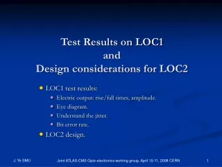
Test Results on LOC1 and Design considerations for LOC2 LOC1 test results: Electric output: rise/fall times, amplitude. Eye diagram. Understand the jitter. Bit error rate. LOC2 design. Joint ATLAS-CMS Opto-electronics working group, April 10-11, 2008 CERN
LOC1 block diagram Ref. clk Control + configuration PLL + clock unit • Five function blocks: the input 8B/10B encoder, the 20:1 serializer, the output driver, the PLL and clock unit, and the control and configuration. • Solid line box: implemented; dashed line box: not implemented. • Loc1 is the 1st prototype only good for tests in lab. 5:1 DFF based serializer 2:1 mux 5:1 DFF based serializer 16 bit data 8B/10B encoder 2:1 mux 5:1 DFF based serializer 2:1 mux 5:1 DFF based serializer to VCSEL Current driver to VCSEL Output driver CML signal CML driver Joint ATLAS-CMS Opto-electronics working group, April 10-11, 2008 CERN
LOC1 basic electrical characteristics • Input power supply: 2.5V (Analog/Digital), 3.3V VCSEL • Power consumption (with current configuration) ~200mW. • Input data signals LVCMOS 2.5V Reference clock 62.5MHz 20bit 8B/10B encoded input data Joint ATLAS-CMS Opto-electronics working group, April 10-11, 2008 CERN
LOC1 test system diagram Data Clock distribution LVDS Driver Board LVDS Interface Board LOC1 Carrier Board Clock FPGA: PRBS generator 8B/10B encoder Error detection Electrical Differential Test point Data TLK Interface Board TLK Carrier Board LVDS Receiver Board I/O to PC FPGA Board Clock • Tektronix 20GHz real-time oscilloscope (DSA72004) and Anritsu BERT were used for the tests. • The VCSEL driver is not functioning. All tests were carried out through the CML driver on electrical signals only. • Signal amplitude, rise/fall times measurement and jitter analysis were performed at the test point (see figure). • BER was measured with the Anritsu BERT. Joint ATLAS-CMS Opto-electronics working group, April 10-11, 2008 CERN
Rise/Fall time and Amplitude • The logic in the digital part, and the PLL + clock unit are functioning as designed. The output serial bits are correct, checked on the scope. • The differential signal amplitude is about 240mV, measured by a differential probe. This is much lower than the 400 mV design spec. The reason of this problem is known and will be fixed in LOC2. • Rise/Fall times are data pattern dependent, measured to be around 150ps. This is boarder line for 2.5 Gbps signal. The reason is not known. The whole driver design will be abandoned. We will use a new driver design in LOC2. Comma (k28.5) code on differential electrical channel Joint ATLAS-CMS Opto-electronics working group, April 10-11, 2008 CERN
Eye diagram • An eye diagram is measured. • There is huge jitter generated inside the chip. • Careful measurements were carried out to identify the components as well as possible sources of this jitter. • We think that we understand this problem very thoroughly. The huge DJ comes from the 4-arm 2-stage mux serializer design. This architecture is not necessary. New serializer design will be implemented in LOC2 to address this problem. • The RJ comes mostly from the PLL. Efforts are spent to improve the PLL design for LOC2. Eye diagram of the Input 27-1 Pseudo random data. UI = 400ps, for 2.5 Gbps. Joint ATLAS-CMS Opto-electronics working group, April 10-11, 2008 CERN
Jitter measurement method • DSA72004 employs software package TDSJIT3 for jitter analysis. • Sample records at 40ps and up to 50M data points in one data file — a snapshot of 2ms waveform length, for long term jitter analysis. • Algorithm performed in the frequency domain. • RJ and DJ components are extracted. Joint ATLAS-CMS Opto-electronics working group, April 10-11, 2008 CERN
Jitter measurement with TDSJIT3 Jitter spectrum Results: RJ_rms = 10ps, DJ_pk-pk = 230ps. Out of 230 DJ, the periodic jitter coming from the serializer structure is175ps. This can be eliminated in LOC2. Total jitter (@10-12 BER) = 310ps. Reminder: UI = 400ps. Joint ATLAS-CMS Opto-electronics working group, April 10-11, 2008 CERN
Periodic jitter • A large periodic jitter is observed. • This strong data dependent, n×492KHz jitter structure (2.5GHz/127/40 = 492KHz) is a clear indication that the jitter comes from an unmatched 4-arm 2-stage serializer. • New serializer structure will be implemented in LOC2 to address this problem. Joint ATLAS-CMS Opto-electronics working group, April 10-11, 2008 CERN
BERT signal generator FPGA board 62.5MHz 2.5GHz 62.5MHz 20bit Data BERT Error Detect LOC1 Serialized Data BER Bit error rate measurement The input amplitude is 110mV because of the Differential to single-ended converter. The BER measurement system We use Anritsu MP1763/1764 BER Tester for this test Joint ATLAS-CMS Opto-electronics working group, April 10-11, 2008 CERN
The bathtub curve The bathtub curve at 2.5Gbps, the best BER reached is ~10-11. • By shifting the reference clock with respect the parallel data, we get the bathtub curve. • From this curve we extract: DJ_pk-pk = 235ps, RJ_rms =18ps, and total jitter = 478ps (@10-12 BER) • The low signal amplitude might cause the large RJ measurement. • The BERT error detect requires 250 mV amplitude input, but our input is 240mV/2 ~ 110mV. Joint ATLAS-CMS Opto-electronics working group, April 10-11, 2008 CERN
LOC2 block diagram Cntrl/Config Cntrl config Clk_ref PLL + clks 27-1 PRBS 8B/10B Comma MUX Data 16 bit Input register LVDS to LVCMOS 2:1 MUX to 8 bit 16 LVDS 10 bit Even bits shift register Serial output to Versatile Link CML driver 2:1 MUX Odd bits shift register Latch The preliminary LOC2 block diagram • We aim LOC2 for a usable chip for “users” to implement in their systems. • A design document is being drafted and circulated for experts’ opinions. • A design document review with people from ATLAS LAr and ID (users + designers) will be held in ~2-3 weeks time frame. • A design review will be held end of 2008. We aim for a submission in early 2009, and make the chip available mid-2009. Joint ATLAS-CMS Opto-electronics working group, April 10-11, 2008 CERN
LOC2 key features • A Serializer at 3.125Gbps or higher speeds; • Differential electrical output (CML), to be coupled to the Versatile Link input; • Compatible with commercial GBE receivers (8B/10B encoder); • 16 bit LVDS differential data input; • Differential 156 MHz reference clock; • Data sampling at rising or falling edge of the reference clock • Internal 27-1 PRBS; • Single 2.5 voltage power supply. Joint ATLAS-CMS Opto-electronics working group, April 10-11, 2008 CERN
Conclusion • LOC1 is under tests at SMU. The testing results provide a lot of information for LOC2 design. • Irradiation tests on LOC1 will be carried out June/July 2008. • The design on LOC2 started. A design document is being generated and a design review will be held April 2008 in the community. • We aim for a submission early 2009 and having chips mid-2009. Joint ATLAS-CMS Opto-electronics working group, April 10-11, 2008 CERN