Download
1 / 39
390 likes | 427 Views
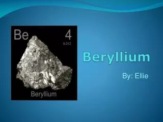
Status Report: Experimental investigation of beryllium. Viacheslav Kuksenko, Steve Roberts University of Oxford, UK. Content Context of the research Materials, points of interest Status of different parts of the experimental program Conclusions. http://www-radiate.fnal.gov.

E N D
Status Report: Experimental investigation of beryllium Viacheslav Kuksenko, Steve Roberts University of Oxford, UK
Content • Context of the research • Materials, points of interest • Status of different parts of the experimental program • Conclusions
http://www-radiate.fnal.gov Investigation of the radiation response of structural window and target materials in new highly intensity proton accelerator particle sources Berylliumis a promising candidate because of: • good “nuclear” properties; • appropriate mechanical properties • good “thermal” properties (conductivity, specific heat, melting point); • high oxidation resistance; • positive experience from existing beam windows What about new working conditions?
Irradiation conditions Long-Baseline Neutrino Experiment (LBNE) Size: Target: L = 950 mm, D = 15.3 mm (48 sections) Window: 25.4 mm diameter, 0.25 mm thick
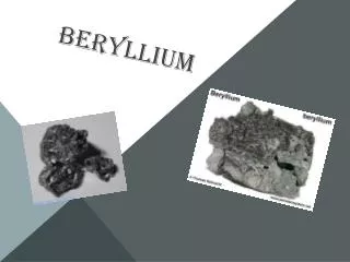
Materials PF-60 S-200-F S-65
Goodfellow order: PF60 5x5x0.5mm 25samples S-200F 5x5x0.5mm 10 samples S-65 5x5x0.5mm 10 samples Arrived, stored in RAL Method of manufacture: vacuum hot pressing
What can we expect during irradiation? • Microstructural response: • creation and agglomeration of point defects; • creation of transmutation products; • segregation (precipitation) or depletion on point defect sinks TE-56 beryllium, Chakin and Ostrovsky / JNM 2002 • Possible irradiation effects: • reduction of fracture toughness • irradiation induced hardening • reduction of ductility • reduction of thermal conductivity
Experiments: Experiments: Investigation of the as-received Be Investigation of the existing proton Be windows - “real” GeV proton irradiation; • irradiated volume is big enough for microstructural investigations and micromechanical tests Simulation with ion irradiation experiments - flexibility of irradiation conditions - observations of the evolution of the microstructure; - reasonable correspondence of He/dpa ratio. Low energy in-situ irradiation: • easy variation of irradiation parameters; High-energy irradiation + PIE • microstructural and micromechanical tests data will be available
Characterisation of as-received Be TE-56 beryllium, Chakin and Ostrovsky / JNMm 2002 Local misorientation around indents made in pure Zr measured using EBSD From http://energy.materials.ox.ac.uk/nuclear-projects/previous-projects/hydride-cracking-in-zirconium.html Grain size Texture Precipitates Dislocation structure SEM + EDX + EBSD TEM ( + APT)
Samples preparation Difficulties: Be dust is very toxic TEM and APT – focused ion beam technique. The place is under consideration. Most probably in CCFE lab
TEM sample Sharpening preparation of samples FIB lift out APT sample FIB lift-out • minimize the toxicity of samples
Samples preparation Difficulties: Be dust is very toxic TEM and APT – focused ion beam technique. The place is under consideration. Most probably in CCFE lab SEM+EDX+EBSD: should be mechanically mirror-polished up to colloidal silica (for EBSD) - under development
Samples preparation Polishing machine for Be - repaired and cleaned. Polishing procedure was developed
Samples preparation • Be polishing will be made in the clean lab (used for Ta activity) at Science park in Begbroke • The procedure of the mechanical polishing will be made in several steps: • primary polishing with SiC paper (Grade P2500), • polishing with diamond paste (6 µm and 1 µm) • final polishing with colloidal silica (0.06 µm). • Test polishing of non-hazardous samples was approved by the Safety office. • Some modifications will appear at the new site, final check with the safety office will be done • Occupational Health assessment - waiting for the information • Measurements of contamination level (air and surface) should be organised • Microstructure characterisation: EBSD trainings are in progress. The quality of Zr samples was relatively low, probably because of lack of water during the last polishing stage
NuMI beam window experiments Brian Hartsell, Fermilab 300 kW NuMI beam window (MARS calculations of Brian Hartsell, Fermilab) • 120GeV proton beam • about 3×10¹³ protons per pulse, 0.5 Hz • 1.57×10²¹ protons during its lifetime • 1.1mm beam sigmas, X and Y • T ≈ 200ºC Total protons, 1020 protons per week, 1018
NuMI beam window experiments Gaussian distribution of the beam • Radiation damage distribution is not monotonic We need to quantify the exposure http://www.livephysics.com
300 kW NuMI beam window (MARS calculations of Brian Hartsell, Fermilab) • 120GeV protons • 1.57×10²¹ protons during its lifetime
NuMI beam window experiments 300 kW NuMI beam window (MARS calculations of Brian Hartsell, Fermilab) • 120GeV proton beam • 1.57×10²¹ protons during its lifetime The main transmutation products are He and H
300 kW NuMI beam window (MARS calculations of Brian Hartsell, Fermilab) • 120GeV proton beam • 1.57×10²¹ protons during its lifetime • The quantity of Li is not negligible (up to 500 appm in the center) • APT for experimental validation of MARS code
NuMI beam window experiments Sharpening Nano-hardness measurements: • to find the Gaussian peak • to estimate the irradiation effect Local microstructural investigations APT TEM
300 kW NuMI beam window Spreadsheet for dose/appm is done The activity calculations need to be crosschecked: Fermilab, my calculations, M.Gilbert (CCFE) Can the activity be measured? Activity of the window will affect the further steps, first of all – the place of samples preparations and experiments
Brian Hartsell, Fermilab We need to know the evolution of radiation effects over the time Collaboration with HiRadMat project Ion irradiation experiments
Experiments: Simulation with ion irradiation experiments - flexibility of irradiation conditions - observations of the evolution of the microstructure structure; - reasonable correspondence of He/dpa ratio. Low energy in-situ irradiation: • easy variation of irradiation parameters; High-energy irradiation + PIE • microstructural and micromechanical tests data will be available
He implantation experiments. Low energy Microscope and Ion Accelerator for Materials Investigations facility (MIAMI) University of Huddersfield , UK (collaboration with Prof. S E Donnelly) Ions: He+ Beam energy: ~ 10keV => peak of damage in the middle of TEM foil (SRIM) Dose: up to1 dpa Temperature: 200ºC (300ºC, 600ºC) From http://www.hud.ac.uk/research/researchcentres/emma/miami/
He implantation experiments. Low energy Fe-9Cr alloy, 150keV Fe+ ions irradiation, 300ºC • In-situ observations of the evolution of the microstructure • evolution of number density and size of dislocation loops and/or He; • Burgers vector and loops nature determination* • But: effect of the surface Irradiation Irradiation of APT tips?
Low energy ion irradiation: Approval of CCFE for Be FIB activity should be received Next step: preparation of samples. First samples – without flash polishing.
He implantation experiments Surrey Ion Beam Centre, UK (collaboration with Prof. R.Gwilliam) Ions: He+ Maximum beam energy: 2 MeV => 7.5µm implantation depth (SRIM) Dose: up to1 dpa Temperature: 200ºC (100ºC, 600ºC) TEM sample APT sample Micromechanical tests Pt 8 × 8 µm3 Pre-tip
Useful where only small samples are available (implanted layer) Need for a sample design that can be machined in surface of bulk samples Geometry that can be manufactured quickly and reproducibly Why use micro-cantilever testing? 0.3mm Stress (Pa) Beam Thickness 2um Strain Chris HardieUniversity of Oxford Fe 6%Cr
Necessary depth 0.65MeV 0.4MeV 1MeV 0.2MeV 1.5MeV 1.75MeV 2MeV • High energy ion irradiation: • Damage peck from He implantation is very narrow: • chain implantation (15 energies); • tilt of the sample; • use of degrader (Al foil)
High energy ion irradiation: • mechanical polishing procedure should be finished; • irradiation conditions should be determined.
Conclusions • Experimental investigation of beryllium within Radiate project should cover 3 main goals: • characterization of existing GeV proton irradiated Be samples; • simulation of proton irradiation effect by ion implantation experiments; • prediction of the microstructural evolution for new irradiation conditions. • Top-priority steps: • final approval of the mechanical polishing procedure (will clear the way for microstructural investigations and samples preparation for high-energy ion irradiation experiments); • clarity with FIB (for TEM, APT, micromechanical tests and low-energy ion irradiation experiments). • The main difficulty: time consuming safety aspects
Strategy of the experimental program : • Beryllium in as-received state: grain size, existing precipitates, dislocations, homogeneity of impurities. • Beryllium in irradiated state: • Investigation of the existing Be window (NuMi from Fermilab) • Ex-situ and in-situ irradiation experiment • What do we expect to do? • Investigation of the existing Be window • One of the main difficulties – preparation of the samples - FIB. • Microstructure, TEM, APT, SEM+EBSD. • A-a Voids and loops. • A-b-Transmutation products exp vs simulation • A-c Amorphisation (clusters, BeO)? • b) Mechenical properties. • B-a Microhardness, microcantelivers. • c) in-situ ion irradiation of (Simulation of proton irradiaiton by He implantation experiments); Evolution of the microstructure as a function of flux, fluence and temperature
introduction: basics of radiation damage - microstructural consequences < What do we know? enhancement of phase transformation agglomeration of point defects ● self-interstitials - clusters; - dislocation loops. o vacancies - voids; - dislocation loops. X - self interstitial atom; clusters of point defects segregation (precipitation) or depletion on point defect sinks voids (He bubbles) inverse Kirkendall effect precipitates If depletion of A atoms grain boundary drag effects dislocation line B-V complexes Segregationof B atoms or dislocation loop B-I complexes V- vacancy; I - interstitial
Tested Cantilevers Unimplanted W+/He+ Load (um) Helium has complex effects on both yield and fracture properties of tungsten Differences between results for micro-cantilevers and nanoindentation show the difficulty of relying on one type of test DEJA -Manchester March 2013 35 Disp (nm) 20/12/2019
Content • Beryllium • Irradiation conditions for beryllium • Experimental program • 3 Be grades. We need to classify: grain size, precipitates, dislocations, texture, homogenity of elements. • What do we expect to do? • Investigation of the existing Be window • One of the main difficulties – preparation of the samples - FIB. • Microstructure, TEM, APT, SEM+EBSD. • A-a Voids and loops. • A-b-Transmutation products exp vs simulation • A-c Amorphisation (clusters, BeO)? • b) Mechenical properties. • B-a Microhardness, microcantelivers. • c) in-situ ion irradiation of (Simulation of proton irradiaiton by He implantation experiments); Evolution of the microstructure as a function of flux, fluence and temperature
Current and future Be spallation target operating conditions* Possible irradiation effects: • reduction of fracture toughness • irradiation induced hardening • reduction of ductility • reduction of thermal conductivity * From: Literature Review On The Irradiation Response Of Be, W And Graphite for Proton Accelerator Applications/ R.B. Jones (BazNutec), G. Hall (University of Manchester), B. Marsden (University of Manchester) and C. A. English (NNL)// . NNL (13) 12703. Issue 1
dose, temperatureand He concentration dependence Radiation damage PIE of Be windows/targets Ion irradiation and implantation experiments TEM defect clusters and He bubbles beheviors of impurities (precepitations, segregations at point defect sinks APT Micromechanicaltests changes of mechanical properties
Precipitates Fe and Al rich precipitates may affect ductility and creep strength (A.W. Jones, R.T. Weiner, J. Common Met. 6 (1964) 266.) Grain, twin and sub-grain boundaries and dislocations can be the preferential places for precipitation of Fe-rich phases during ageing of Be-0.25%Fe. Dislocation can locked by precipitates leading to the increase of hardness (S. Morozumi, N. Tsuno, S. Koda, Trans. Jpn. Inst. Met. 10 (1969) 64.) Intermetallic Fe/Al/Be inclusions are the preferential sites for corrosion pit initiation, some corrosion pits had also initiated at elemental Si and carbide inclusions. (J.S. Punni, M.J. Cox, Corros. Sci. 52 (2010) 2535) Al and Mg can form low melting point eutectics in Be, that might influence the mechanical behaviour of Be. e^(-((x^2)/3+(y^2)/3))