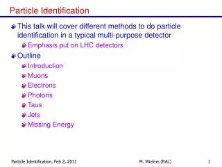
Particle Identification
Particle Identification. Graduate Student Lecture Part 1 Warwick Week . S.Easo, RAL 19-20 April 2012. Outline. Lecture 1 :. Introduction Cherenkov Detectors. Main techniques for Particle Identification (PID) Main principles Photodetectors


Particle Identification
E N D
Presentation Transcript
Particle Identification Graduate Student Lecture Part 1 Warwick Week S.Easo, RAL 19-20 April 2012
Outline Lecture 1 : • Introduction • Cherenkov Detectors • Main techniques for Particle Identification (PID) • Main principles • Photodetectors • Example of large Cherenkov Detector in HEP Lecture 2 : • Detectors using Energy Loss (dE/dx) from ionization • and atomic excitation • Time of Flight (TOF) Detectors • Transition Radiation Detectors (TRD) • More Examples of PID systems • Astroparticle Physics • Not Covered : PID using Calorimeters • Focus on principles used in the detection methods.
Introduction • Particle Identification is a crucial part of several experiments in Particle Physics. • Identify Pions, Kaons, Protons, electrons, muons, tau etc. • Tracking+Magnet : Measure the direction and momentum of charged particles • Calorimeter: Measure the energy deposited in an Electromagnetic • or Hadronic shower created by the particles. • PID: • Use information from Tracking and Calorimeters alone. • Detection of muon tracks in the downstream most ‘tracking’ detectors. • (c) Use additional information from ‘Particle Identification’ detectors . • ‘PID’ detector: • Reduction of combinatorial backgrounds • More examples and other uses of PID detectors • later in the lecture. Calorimeters and tracking detectors covered in other lectures. f -> K+ K - from HERAB
Cherenkov Detectors • Cherenkov Radiation: General Ideas • Brief History of the development of Cherenkov detectors • Classification of Cherenkov detectors • Photo detectors to detect Cherenkov Radiation • Examples of large Cherenkov Detector systems
Basics of Cherenkov Radiation photon q Charged particle cos(q) = 1/ (n b) where n = Refractive Index = c/cM = n(E ph) b = v/c = p/E = p/ (p2 + m 2)0.5 = 1/(1+(m/p)2)0.5 • = velocity of the charged particle in units of speed of light (c) vacuum p, E ,m = momentum, Energy, mass of the charged particle. CM = Speed of light in the Medium (Phase velocity) , Eph= Photon Energy, l=Photon Wavelngth. • Theory of Cherenkov Radiation: Classical Electrodynamics by J.D.Jackson ( Section 13.5 ) • The energy radiated by the charged particle as Cherenkov Radiation per unit length = • dE/dx = (Z/c)2w (1-1/(b2 e (w)) ) dw • e(w) > 1/b2 Where w= Frequency e(w) = n2 = permittivity assume permeability =1 Z= charge of the particle Typical example: Charged particle with momentum of few GeV/c or more emitting Cherenkov photons with few eV of energy
Basics of Cherenkov Radiation cos(q) = 1/ (n b) • = 0 : Cherenkov Threshold for the charged particle. At Threshold, b= 1/n q has Maximum in a medium when b almost = 1 p/msufficiently high Saturated Tracks • Particle ID: q ( p,m) ; If we measure p and q , we can Identify different particles with different m. • Typically, in Accelerator based experiments, Momentum (p) is measured by a Magnetic Spectrometer : Tracking detectors and a Magnet. • Cherenkov Detectors: Measure q : Resolution can be expressed in terms of ( D b / b ) Photonic Crystals: No Cherenkov Threshold and q >90 degree. Not covered in this lecture: Reference: http://ab-initio.mit.edu/photons
Basics of Cherenkov Radiation Cherenkov Angle vs Charged Particle Momentum
Components of a Cherenkov Detector • Main Components: • Radiator : To produce photons • Mirror/lens etc. : To help with the transport of photons • Photodetector : To detect the photons • Radiator: Any medium with a Refractive Index. Aerogel: network of SiO2 nano-crystals g = 1/sqrt(1-b2) • The atmosphere, ocean are the radiators in some Astro Particle Cherenkov Detectors
Note on the History of Cherenkov Radiation • The formula cos (q ) =1/(nb) was already predicted by Heaviside in 1888 • ~1900: ‘Blue glow’ seen in fluids containing concentrated Radium (Marie & Pierre Curie) • Pavel Alexeevich Cherenkov (1904-1990): Lebedev Physical Institute of the Russian Academy of Sciences. • Discovery and Validation of Cherenkov Effect : 1934-37 • Full Explanation using Maxwell’s equations: I.M. Frank and I.E. Tamm in 1937 • Nobel Prize in 1958: Cherenkov, Frank and Tamm.
History of Cherenkov Radiation • 1: vessel with liquid • 2 mirror • 3: Cherenkov photons towards the photographic plate Typical Apparatus used by Cherenkov to study the angular distribution of Cherenkov photons. (Incident g ray produces electrons by compton scattering in the liquid). P. Cherenkov established that: • Light Intensity is proportional to the electron path length in the medium. • Light comes only from the ‘fast’ electrons above a velocity threshold, in his Apparatus. • Light emission is prompt and the light is polarized. • The wavelength spectrum of the light produced is continuous. No special spectral lines. • The angular distribution of the radiation, its intensity, wavelength spectrum and its dependence on the • refractive index agree with the theory proposed by his colleagues Frank and Tamm.
Photons from Cherenkov Radiation • n= n(l) : Different photons from the same charged track can have different Cherenkov Angles.(Cos (q)=1/n b)). This spread in angles gives rise to ‘Chromatic Error’ when measuring the average q. • To reduce the Chromatic error various methods have been tried: • Filter out the low wavelength photons before they reach the photodetector. • Appropriate choice of the radiator material • Recent development: Measure the Time-Of-Propagation of photons • to estimate their wavelengths and correct for the Chromatic Error. • ( Time= ( PathLength in the detector) / Velocity )
Photons from Cherenkov Radiation • Current photon detectors used for detecting Cherenkov light are sensitive to visible + part of UV. This part of the EM spectrum produced by the Cherenkov Radiation is the only range relevant for Cherenkov detectors. lphranges from 135 nm to 800 nm depending upon the photodetector. • Number of photons produced by a particle with charge Z , along a Length L : (From Frank-Tamm theory) Nprod = (a/hc) Z2L sin2(q) dEph where a/hc = 370 eV-1cm-1 , Eph= hc/l. • If the photons are reflected by a Mirrror with Reflectivity R(Eph ), are transmitted through a quartz window of Transmission T(E ph ) and then are detected by a photon detector with efficiency Q (Eph) • Number of photons detected : Ndet = (a/hc) Z2L R Q T sin2(q) d E ph = N0 L sin2(q c) ( If we assume q is constant = qc = Mean Cherenkov Angle ) • Figure of Merit of the detector = N0 For example, N0 = 200 cm -1 is a good value.
Classification of Cherenkov Detectors • Cherenkov Detector Designs: • Threshold Counters • Imaging Counters: • Differential Cherenkov Detectors • Ring Imaging Cherenkov Detectors (RICH) • Detector for Internally Reflected light (DIRC) • Types of Photodetectors: (a) Gas Based (b) Vacuum Based (c) Solid State • Applications: • In Accelerator Based High Energy Physics Detectors • In AstroParticle Physics Detectors
Differential Cherenkov Detectors With Solid (quartz) radiator • Discovery of anti-proton in 1955 by Chamberlain, Segre et. al. at Berkeley. • Nobel Prize in 1959
Differential Cherenkov Detectors With a Gas radiator
Differential Cherenkov Detectors • Very small acceptance in b and direction of the charged particle. (Narrow range in velocity and direction intervals ). • From the Cherenkov angle (q ) determine b. • Mostly used for identifying particles in the beam lines. • Resolution that can be achieved = D b/ b = (m12 – m22) /2 p 2 = tan q Dq m1,m2 (particle masses )<< p ( momentum) • At high momentum, to get better resolution, use gas radiators which have smaller refractive index than solid radiators. Have long enough radiators to get sufficient signal photons in the detector. • To compensate for Chromatic dispersion (n (Eph) ) , lens used in the path of the photons. (DISC: Differential Isochronous self- collimating Cherenkov Counter). • Db/ b from 0.011 to 4* 10 -6 achieved.
Threhold Cherenkov Counters • Signal produced from only those particles which are above Cherenkov Threshold. Basic version: Yes/No decision on the existence of the particle type. • One counts the number of photoelectrons detected. • Improved version: Use the number of observed photoelectrons or a calibrated pulse height to discriminate between particle types. • For typical detectors: No = 90 cm-1, Nph per unit length of the radiator = No * (m12 – m22)/(p2+m12) At p= 1 GeV/c, Nph per unit length = 16 /cm for Pions and 0 for Kaons. At p= 5 GeV/c, Nph per unit length= 0.8 /cm for Pions and 0 for Kaons. • Db / b = tan2q / (2 * sqrt (Nph) )
Threshold Cherenkov Detectors • Can be used over a large area, for Example : For secondary particles in a fixed target or Collider experiment. • E691 at Fermilab: To study decays of charm particles in the 1980’s Db/b = 2.3 * 10-5 using gas radiator. • BELLE Experiment: To observe CP ciolation in B-meson decays at an electron-positron collider. • BELLE: Continues to take Data.
Threshold Counters BELLE: Threshold Cherenkov Detector • Five aerogel tiles inside an aluminum box lined with a white reflector(Goretex reflector) • Performance from test- beam • Approx . 20 photoelectrons per Pion detected at 3.5 GeV/c • More than 3s separation p below and p above Threshold
RICH Detectors • Measures both the Cherenkov angle and the number of photoelectrons detected. • Can be used over particle identification over large surfaces. • Requires photodetectors with single photon identification capability.
RICH detectors • Db / b = tan(q) * Dqc = K where Dq c = < Dq > / sqrt(N ph )+ C where <Dq> is the mean resolution per single photon in a ring and C is the error contribution from the tracking , alignment etc. • For example , for 1.4 m long CF4 gas radiator at STP and a detector with N0 = 75 cm-1 K = 1.6 * 10 -6 . ( E=6.5 eV, DE = 1 eV) • This is better than similar Threshold counters by a factor 125. This is also better than similar Differential counters by a factor 2. Reason: RICH measures both q and Nph directly. • RICH detectors have better resolution than equivalent Differential and Threshold counters. • Let u= sin2 (q) = 1- (1/n2) - (m/p*n) 2 Number of standard deviations to discriminate between mass m1 an m2 = N s = (u2-u1) / ( su * sqrt( N)) where su : D q converted into the parameter u. ( D q = error in single photon q measurement) • At momentum p (=b E), p= sqrt((m22-m12)/(2* K * Ns )) , for b ~1 This equation can be used in the design of the RICH detectors. • One the first large size RICH detector: in DELPHI at LEP.
Detection of Photoelectrons • Principle: • Convert Photons Photoelectrons using a photocathode • Detect these photoelectrons using ‘charged track detectors’. • Measure the position and (/or ) time of photoelectrons in the tracking detector. • General introduction to tracking detectors is not covered in this lecture. Introduction to Silicon detectors already covered in another lecture of this series. • In this lecture, we focus on some of the aspects related to the detection of photoelectrons in Cherenkov Detectors. • Gas based detectors: • MWPC (Multi Wire Proportional Chambers) • GEM (Gas Electron Multiplier ) • Vacuum based detectors: PMT (Photomultiplier tubes) HPD (Hybrid Photodiodes) • Solid state detectors: Silicon photomultipliers
Photodetectors • Photon Conversion: • Photoelectric Effect : Photon energy to be above the ‘work function’ (Einstein : Nobel Prize in 1921). • Commercial alkaline Photocathodes: Bialkali , Trialkali (S20) , CsI etc. Alkali metals have relatively low ‘work function’. • There are also gases where the photon conversion takes place. • Different photocathodes are efficient at different wavelength ranges. • Quantum Efficiency (QE) : Fraction of photons converted to electrons Examples of S20- photocathodes
Gas Based Photon Detectors • QE: 33% at 150 nm • Spectral Range: 135-165 nm • TEA: Triethylamine Photon Detector of the CLEO-III Cherenkov detector • photon passes through the CaF2 and converts to photoelectron by ionizing a TEA molecule. • The photoelectron drifts towards and avalanches near the anode wires, theirby inducing a charge signal on the cathode pads.
CAPRICE Experiment Balloon Experiment: RICH detector TMAE: (tetrakis(dimethylamino) ethylene)
Photodetector with CsI photocathode • Used in ALICE experiment at CERN • Thickness of : • radiator = 10mm • quartz window= 5mm • MWPC gaps= 2 mm • Wire cathode pitch=2 mm • Anode pitch= 4 mm • anode diameter= 20 micron • pad size = 8*8 mm2 • Total detector area: 12 m2 • Open geometry: using MWPC Proximity focussing photon Backscatterd electron Electron transport region (diffusion) Typical gain: 104 photon cause feedback: leading to loss of original signal info.
Recent Developments: Gas Based Photodetectors GEM: Gas Electron Multiplier GEM with semi-transparent Photocathode (K-Cs-Sb) • Photon and ion feed back reduced. • Gated operation to reduce noise. (no readout outside a ‘time window of signal’) • For now only closed geometry ( in sealed tubes): Reduced fraction of useful area for photon detection (Active Area Fraction) compared to open geometry.
Vacuum Based Photodetectors PMTs MAPMT • PMTs Commercially produced: more info in www.sales.hamamatsu.com Silicon detector of HPD HPD
Features of HPD Signal pulse height spectrum of a 61-pixel HPD Illuminated with Cherenkov photons • Band gap in Silicon = 3.16eV; Typical Max Gain = 20 keV / 3.16 eV = 5000 (approx)
Features of the PMTs and HPDs • PMT: • Typical Gain of MAPMT 300 K. • Excellent time resolution: 125 ps for example (Ex: used in underwater Cherenkov detectors). • Active area fraction: 40 % : Fraction of effective detection area. This can be Improved with a lens, but then one may loose some photons at the lens surface. • Recent developments: Flat panel pmts with 89 % active area fraction. New photocathodes with >45% QE at 400 nm • HPD: • Typical gain 5K, but quite uniform across different channels. • Excellent Single photon identification capability. • Active area fraction: 35 76 %
Comparison of photodetectors • Choice of photodetector depends on the design of the Cherenkov detectors and constraints on cost etc. • Gaseous: Issues: • Related to photon and ion feed back and high gains at high rate. • Detection in visible wavelength range (for better resolution) • Can operate in high magnetic field • Lower cost for large size detectors compared to vacuum based Advantages: • Vacuum based: Issues: • Sensitivity to magnetic field • cross talk between readout channels in case of MAPMTs • Active Area Fraction Advantages: • Can easily operate at high rate (eg. LHC rates and higher). • Operates also in visible wavelengths. • Ease of operation at remote locations: underwater, in space etc. • HPD: uniform gain over large number of tubes and small noise. • Other Types and new developments: APD, Silicon photomultiplier, HAPD , MCP etc.
Recent Developments:Silicon Photomultipliers • Photon Detection Efficiency (PDE) for SiPM about 5 times that of ordinary PMT. • Time resolution= ~ 100 ps. • Works in magnetic field • gain = ~ 10 6 • Reducing noise levels for single photon • detection is still an issue and is being worked upon.
New Developments: Micro Channel Plate (MCP) Photon Detectors
New Developments: Micro Channel Plates (MCP ) • Typical Size: • 2 mm thickness, • 51 mm X 51 mm active area. • 10 micron pores separated by 15 microns • Chevron: 8 degree tilt : To increase • th gain and reduce ion-feed back • Gain: ~ 5 * 10 5 • Typically ~ 1000 channels per MCP. • Measure Space and time of the hits. • Manufactured by industry ( Photonics for example). • Resolutions: Space: ~100 microns, Time: ~ 50 - 100 psec. • Short flight path of photoelectrons: Resistant to magnetic fields up to 0.8 Tesla. • Can work at 40 MHz readout rate. • Can detect single photons ( No noise from ‘first dynode’ as in MAPMT). • Fast ‘ageing’ at large luminosity (eg: LHC) is an issue, but there are some solutions.
LHCb Experiment • Precision measurement of B-Decays and search for signals beyond standard model. • Two RICH detectors covering the particle momentum range 1100 GeV/c using aerogel, C4F10 and CF4 gas radiators.
LHCb-RICH Design RICH1: Aerogel L=5cm p:210 GeV/c n=1.03 (nominal at 540 nm) C4F10 L=85 cm p: < 70 GeV/c n=1.0014 (nominal at400 nm) Upstream of LHCb Magnet Acceptance: 25250 mrad (vertical) 300 mrad (horizontal) Gas vessel: 2 X 3 X 1 m3 RICH2: CF4 L=196 cm p: < 100 GeV/c n =1.0005(nominal at 400 nm) Downstream of LHCb Magnet Acceptance: 15100 mrad (vertical) 120 mrad (horizontal) Gas vessel : 100 m3
LHCb-RICH Specifications (Refractive Index-1) vs. Photon Energy RICH1: Aerogel 210 GeV/c C4F10< 70 GeV/c RICH2: CF4 <100 GeV/c. n=1.03 n=1.0014 Aerogel C4F10 CF4 L 5 86 196 cm qcmax 242 53 32 mrad pTh 0.6 2.6 4.4 GeV/c KTh 2.0 9.3 15.6 GeV/c n=1.0005 Aerogel Transmission Aerogel: Rayleigh Scattering T = A e(-C t /l4) Typically: A= 0.94, C =0.0059 mm4 /cm
LHCb- RICH1 SCHEMATIC RICH1 OPTICS Magnetic Shield Gas Enclosure Beam Pipe Spherical Mirror Flat Mirror Photodetectors Readout Electronics • Spherical Mirror tilted • to keep photodetectors outside acceptance • (tilt=0.3 rad)
RICH1 Photos RICH1-HPDs RICH1 mirrors
LHCb-RICH2 SCHEMATIC Mirror Support Panel RICH2 Optics Top View Spherical Mirror Support Structure Y X X Z Beam Axis- Z Flat Mirror • Plane Mirrors to reduce the length of RICH2 • Spherical mirror tilted to keep photodetectors outside acceptance.(tilt=0.39 rad) Central Tube Photon funnel+Shielding
LHCb- RICH2 STRUCTURE Entrance Window (PMI foam between two carbon fibre epoxy Skins) RICH2
Typical Hits on LHCb-RICH HPDs Early data in 2010 • In, LHCb-RICH collected data in 2010, 2011. In 2012 it will be taking data. • The signals from the HPDs are subjected to time and space alignment.
Performance of LHCb RICH • From isolated Cherenkov rings from RICH1 in Real Data Compare with the expectations plotted in slide 7.
Example of LHCb-RICH PERFORMANCE • Performance as seen in Simulated Data in 2006 • Yield: Mean Number of hits per isolated • saturated track (Beta ~1). Single Photon Cherenkov Angle Resolutions in mrad. • Chromatic: From the variation in • refractive index. • Emission Point: Essentially from the • tilt of the mirrors. • Pixel Size: From the granularity of the • Silicon detector pixels in HPD • PSF ( Point Spread Function): • From the spread of the Photoelectron direction • as it travells inside the HPD, • (from the cross focussing in the electron optics)
LHCb: Hits on the RICH from Simulation Red: From particles from Primary and Secondary Vertex Blue: From secondaries and background processes (sometimes with no reconstructed track)
Pattern Recognition in Accelerator based Cherenkov Detector • Events with large number of charged tracks giving rise to several • overlapping Cherenkov Rings on the Photo detector plane. • Problem: To identify which tracks correspond to which hits and then identify • the type (e, p, p etc.) of the particle which created the tracks. • Hough Transform: • (used by ALICE • at CERN) • Project the particle direction on to the detector plane • Accumulate the distance of each hit from these projection points in case of circular rings. • Collect the peaks in the accumulated set and associate the corresponding hits to the tracks. • Likelihood Method: • For each of the track in the event, for a given mass hypothesis, create photons and project them to the detector plane using the knowledge of the geometry of the detector and its optical properties. Repeat this for all the other tracks. • From this calculate the probability that a signal would be seen in each pixel of the detector from all tracks. • Compare this with the observed set of photoelectron signal on the pixels, by creating a likelihood. • Repeat all the above after changing the set of mass hypothesis of the tracks. Find the set of mass hypothesis, which maximize the likelihood. (used by LHCb at CERN) (Ref: R.Forty: Nucl. Inst. Mech. A 433 (1999) 257-261)
LHCb-RICH pattern recognition Efficiency for identification and probability for misidentification vs Particle momentum Particle Identification using the likelihood method. MC Data
Typical PID Performance in Real Data From RICH Calibration samples
RICH Data in Physics Analysis f K + K - Status in 2011 using RICH data RICH data has been used in Physics analysis
LHCb-RICH Preliminary data • Examples of signals for F->KK, K s ->pp , D ->Kp , L-> p p obtained using RICH . • The data from RICH used for Physics Analysis.