EXAMPLE PROBLEM 378
This document details the training objectives and design parameters for flood routing in Pond 378, including auxiliary spillway elevation and integrity analysis. It covers key data such as drainage area, hazard classification, permanent pool elevation, and spillway design specifications. Essential calculations include sediment volume, conduit data, embankment dimensions, and soil properties for effective stability and integrity analysis. The analysis incorporates rainfall data and vegetative considerations to ensure reliable performance. Ideal for engineers and professionals in hydraulic and civil engineering.


EXAMPLE PROBLEM 378
E N D
Presentation Transcript
EXAMPLE PROBLEM378 Temple, Texas April 19-21, 2005
TRAINING OBJECTIVES • Be able to flood route a 378 pond
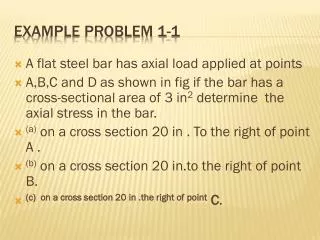
AUX. SPLWY. PERM, POOL INLET CHANNEL CREST AUX.. TOP DAM EXIT CHANNEL TAILWATER ELEV TOP DAM DESIGN FLOW (SDH) CREST AUX. FBH SDH PSH PERM. POOL CONDUIT TAIL- WATER TAIL- WATER CREST PS
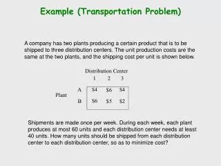
SITES 378 PROBLEM REVISED September 2003 GIVEN: Drainage Area = 103 acres. Hazard Class = A1 RCN = 72 W/S length = 987’ with a slope of 2% Permanent Pool @ Elev. 100.0 feet. Crest of principal spillway = Elev. 100.0 feet Volume of sediment between principal and aux. spw = 0 ac-ft Valley Floor Elevation - 88 feet
Structure Data Elev. (ft)Surface Area (Ac.) 85.5 0 89.5 0.3 96.4 1.2 100 4.8 104.3 10.8 106 11.8
Rainfall: 1 day = 7.5” Design FBH = 8.95” Rain distribution: Read in a 24-hr duration, rain table (TXIII24.RTB)
Principal Spillway Data: (Single Stage) Number of Conduits = 1 Length of Conduit = 114 feet Diameter of Conduit = 12” Conduit “n” = 0.013 Ke = 1.0 HGL at outlet of conduit = 89.5 feet. Riser weir length = 6.28 feet.
CLPROFILE DAM CENTERLINE PROFILE Centerline Dam Valley Profile Data: Station(ft.)/Elev. (ft.) 0/106 43/104.3 73/103 103/100.8 133/99.6 163/98.4 193/96.9 223/96.4 253/93.6 287/89.5 337/94 367/95.2 387/95.8 417/96.9 457/103.3 487/107
Embankment Data: Top Width = 12’ Upstream side slope = 4:1 Downstream side slope = 4:1 Wave Berm Width = 20’ No Stability Berms Crown = 0.5’
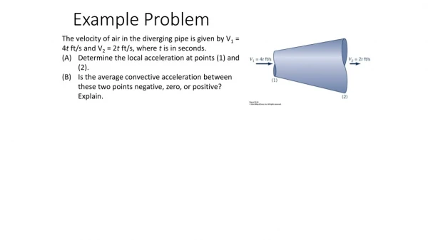
Auxiliary Spillway Data: We want to do a Stability & Integrity Analysis of the Spillway. Let the program set the crest. Station at DS end of Crest = 620 Inlet length of the auxiliary spillway is about 150 ft. Profile or spillway inlet template data (x,y) (distance, drop): 50’/0’; 280’/3.0’ Bottom Width: 30 feet Spillway sideslope = 3:1 Spillway slope 3% (constructed exit channel)
280’ 50’ 3’ Inlet Spillway Template Z = 3:1 BW = 30’
Spillway Geology and Vegetation Data: Material in spillway - Clay (CL) PI or (lw) = 18 The representative soil particle size D75 = 0.0024 inches Percent Clay = 28% (in material in spillway) Dry Density of the clay = 92 pcf Headcut Erodability Index = 0.1 Vegetative Retardance Curve Index = 5.6 (Inlet) Vegetative Retardance Curve Index = 5.6 (Outlet)
Assume 2 foot (2’) of rooting depth in spillway One foot (1’) of topsoil will be installed in the constructed channel The topsoil D75 is 0.02”. Cover Factor (assume good) bromegrass = 0.7 - 0.8 Maintenance Code (assume good in constructed ) = 1 Maintenance Code (assume minor irr. in natural ) = 2
Coordinates of top of material: Sta. (ft.)/ Elev. (ft.) 100/85; 310/95; 410/106; 500/107; 700/106; 750/100; 930/95; 960/90; 1000/84
FIND: The auxiliary spillway elevation and top of dam elevation. Also what is the integrity distance for the spillway analyzed?
Example 2 Use Example 1 as a start Use a Hood Inlet with same diameter and pipe length as the pipe drop. Distance to bend 100’ and bend to outlet 14’. The elevation of the bend is 90 and the outlet is 89. Say the Mannings “n” = 0.013 Circular weir coeff. -- 0.6 Entrance coeff. -- 1.0
Example 2a Use Example 1 as a start Add stability berm on the down stream side at 5’ with 25’ top width.