Download

1 / 38
380 likes | 589 Views
FEMCI Workshop at GSFC 17 May 2001 STOP Analysis & Optimization of a very Low-Distortion Instrument HST WFC3 Case Study by Cengiz Kunt Swales Aerospace, Inc. HST. WFC3. OUTLINE.

E N D
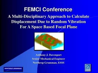
FEMCI Workshop at GSFC 17 May 2001 STOP Analysis & Optimization of a very Low-Distortion Instrument HST WFC3 Case Study by Cengiz Kunt Swales Aerospace, Inc.
HST WFC3 OUTLINE WFC3 (Wide Field Camera 3) is a “radial” instrument under development to replace WF/PC2 (Wide Field Planetary Camera 2) of the Hubble Space Telescope (HST) in the next servicing mission. Presentation Outline Instrument Overview Optical Performance and Requirements Structural-Thermal-Optical Performance (STOP) Analysis Approach Multi-Disciplinary Systems Engineering Approach Key Design Requirements Optical Bench Structure and Materials Detailed Structural Analyses Structural Issues Critical to STOP Optimization Thermal Design and Analysis STOP Analysis Results Gravity Sag and Other Long-Term Short-Term Conclusions and Recommendations
INSTRUMENT OVERVIEW Enclosure (top Panel removed to show the bench) WF/PC2 Hardware (Aluminum Construction) with some Modifications Radiator Optical Bench Houses 2 optical channels: UVIS and IR New Design
WFC3 Optical Bench C Latch Interface Bracket Pick Off Mirror Arm A Latch Interface 8 X Interface Struts OPTICAL BENCH Low distortion characteristics of its Optical Bench are key to the optical performance of WFC3 since it houses all the critical optical components of the instrument. WFC3 is configured as a two-channel instrument. The incoming beam from the HST is directed into the instrument using a pick off mirror and is then sent to either a near-UV/visible (UVIS) channel or a near-IR channel. Optical Bench structure has been analyzed, designed, and fabricated by Swales Aerospace. It is now being assembled at Swales. It will undergo environmental qual testing next month at GSFC.
UVIS Shutter UVIS Detector SOFA UVM1 & Corrector Mechanism Cal Subsystem UVM2 IR Fold IRM1 IR Cold Enclosure/ RCP/Filters/ Detector Pickoff Mirror IRM2 & Corrector Mechanism Channel Select Mechanism OPTICAL BENCH LAYOUT
(milli-arcsec) LINE-OF-SIGHT (LOS) &OPTICAL PERFORMANCE • LOS Error due to the motion of the image across the Detector chip over a two-orbit interval • LOS Error => Short Term Stability => Short Term Distortion Budget • Scientists do not want more than 1/4 of a pixel motion so their software can adequately overlap successive images. If they cannot overlap successive images to this level the images will appear to be blurred and degrade resolution. • Short Term Error Sources: On-Orbit Temperature Variations, Jitter • Based on the Pixel sizes of its channels, the Short-Term Distortion Budget for the WFC3 instrument are: • UVIS Channel: 39/4 10 milli-arcsec • IR Channel: 80/4 = 20 milli-arcsec
WAVE-FRONT (WF) &OPTICAL PERFORMANCE • Light enters the HST telescope as a set of individual parallel light rays that eventually come to focus at the instrument detector. If all the mirrors were perfectly figured and perfectly aligned, then all the light is contained within the tightly focused image at the detector. The size of the spot is then only controlled by diffraction (light bending around edges) due to the size of apertures. When the mirrors move or distort so they are not perfectly aligned anymore, the light rays no longer focus at the same spot on the detector. In other words the ideal wave-front now has an error. • WF Error => Long Term Stability => Long Term Distortion Budget • The WF error does have an impact on resolution. If the WF error gets worse, the spot size on the detector grows larger or odd shaped thereby degrading resolution. • The amount of mirror motion required to distort the image on the detector is actually much larger than the LOS budget. Therefore, the short term distortions have negligible effect on the Wave-Front Error. • WF Error => Long Term Stability => Long Term Distortion Budget • Long Term Error Sources: Gravity Release, Ground-to-Orbit Temperature (Set Point) Change, Desorption, Launch Shift • WFC3 Long Term Distortion Budget 50 arcsec for both UVIS and IR Channels
POINTING (Alignment) ERROR Sum of “Static” and “Dynamic” Errors STATIC ERROR (Long Term or Wave-Front Error, Accuracy) WFC3 Budget 50 arcsec “One-Time” Shift from Ground Alignment to Orbit Operation Major Sources: Gravity Release (Gravity Sag) Temperature Change (Set Point Shift) Moisture Desorption Assembly/Integration Induced Launch Loads Induced (Launch Shift) Mechanically Transmitted Rigid Body Motion Actual Passive Pointing Performance “Uncompensated” for Static Error Pointing Error, Stability: / t t S L E W time, t Fully Compensated for Static Error-Hypothetical (Zero mean error) DYNAMIC ERROR (Short Term or Line-of-Sight Error, Knowledge) WFC3 Budget 10 milli-arcsec for UVIS Channel Major Sources: On-Orbit Temperature Changes Jitter Mechanically Transmitted Rigid Body Motion Compensated for Static Error (Note not fully compensated because of the limitations of the corrector mechanisms) POINTING PERFORMANCEERROR ANALYSIS & SOURCES
Structural Finite Element Model Apply Nodal Temperatures to F.E.M. Thermal Math Model Other Distortion Inducing Inputs, eg; mechanical from Enclosure or Gravity Sag and Desorption for Long Term Recover Displacements of the Optical Components Apply the Sensitivity Matrix Update Thermal Design / Model Code V Optical Model Calculate Resultant Motion at the Detector Update Structural Design / Model Compare with CEI Requirements Meet Allowables? END ANALYSIS NO YES STOP ANALYSIS FLOW
Requirements Definition Testing Multi-Disciplinary Systems Structural Engineering Materials Engineering Thermal Engineering Alignment Planning & Metrology Attitude Control Observatory Operations Design Analysis Manufacturing MULTI-DISCIPLINARYSYSTEMS ENGINEERING APPROACH
OPTICAL BENCHKEY DESIGN REQUIREMENTS • Meet WFC3 Optical Pointing Requirements • Provide support for the WFC3 Optical System and package to fit into existing Enclosure • Provide easy access for components throughout integration • Meet the HST SM4 Structural Requirements • Interface to HST: Meet the flow down requirements of ST-ICD-03F: Space Telescope, Level II, ICD… “Radial Scientific Instruments to Optical Telescope Assembly and Support Systems Module” • Provide an interface with adequate mechanical and thermal isolation from the WFC3 enclosure. • Meet the flow down instrument mass requirements • Meet the HST and Optical System contamination requirements • Support late-in-the-flow change-out requirements of the detectors and filters per the WFC3 CEI spec • Reuse WF/PC1 hardware where possible
OPTICAL BENCH STRUCTURE Top Panel Top cut outs for SOFA access Honeycomb Panel Construction Low CTE Graphite/Epoxy Facesheets UVIS detector bulkhead (4.5) Center bulkhead (3) (contains bench optical reference) Sandwich panel construction Black Kapton film edge closeouts - bonded with EA 9394 UVIScorrectorbulkhead Front bulkhead (1) Rear bulkhead(4) Pick Off Mirror Arm LOS cutouts C LatchInterface Bracket Bottom Panel Side panels (4 X) A Latch Interface 8 X Interface Struts Second bulkhead (2)
UVIS Optics on +Y Side IR Optics on -Y Side B- Latch Latch Models from Existing Enclosure FEM Struts C-Latch A-Latch OPTICAL BENCH STRUCTURAL ANALYSIS &FINITE ELEMENT MODEL (FEM) • NASTRAN (70.5) FEM for Structural Normal Modes and Distortion Predictions • Bench is kinematically supported at A, B, & C Latch Points. • For STOP analysis, FEA predictions manipulated in spreadsheet to calculate Optical degradation • Stress Analysis by NASTRAN FEA and Analytical Calculations • FEM Highlights • Refined for improved accuracy and resolution • Approx. 15,000 nodes (90,000 DOF) and nodal spacing less than 0.5 inch on the average • Plate elements (panels and bulkheads) • Bar elements (struts, POM arm, Optic Representations, interfaces), and • Point Mass Elements (Optic Components)
Enclosure - Bench Coupled FEM A C STRUCTURAL ANALYSISBENCH & ENCLOSURE COUPLED FEM • Finite Element Model (FEM) of OB updated and coupled into the Existing Enclosure FEM. • Assembly is kinematically supported at A,B & C Latch Points • Coupled FEM used for Stress and Distortion Analysis of the Bench • OB standalone FEM used for Normal Modes Analysis.
In-Plane Constraint Direction 3 2 KINEMATIC MOUNTING SYSTEM WFC3 Kinematic Mount System Another Type of Kinematic Mount System No Rigid Body Motion A (1,2,3) Rigid Body Rotation RB Undeformed Uniformly Expanded B (1) C (1,2) Pivoting Kinematic Mount System causes rigid body rotation, RB with proportional differential motion. But RB 0 for a bench with “zero” CTE and “zero” CME.
Enclosure Hanging Beam & Flexures Optical Bench - Center BulkHead C B A V1 Struts & Flexures V2 Existing HST Latch Hardware is primarily Titanium with a “high” CTE. Struts need to be designed with a negative CTE to athermalize the latch-strut assemblies at A, B, and C. ENCLOSURE FLEXURE INTERFACE TO BENCH • Enclosure which is a primarily Aluminum Structure gets bolted to the Latch Interface Plates • It is very important to maintain a “weak” mechanical coupling between the bench and the enclosure to minimize the thermal distortion effects of the enclosure on the bench • “Hanging Beam” and its diaphragm flexures (WF/PC1 Design) isolate the bench from the enclosure the V2 Direction. • Struts and their blade flexures (New Design) isolate the bench from the enclosure in the V3 Direction.
2 2 Hanging Beam 4 4 1 1 A C B 3 3 LS LS LL STRUT - LATCH ATHERMALIZATION • Strut CTE’s determined to negate Short Term Thermally Induced Motions of the Latches based on a Temperature Change Relationship of Tlatches = Tstruts . Latches and Struts are thermally strongly coupled to each other and this is confirmed by thermal model predictions. • 4 pairs of struts with each pair requiring a different negative CTE as calculated below.
b1 b2 a1 d d a2 e e c L STRUT INTERNAL DIMENSIONSFOR STRUT-LATCH ATHERMALIZATION For each strut pair, strut internal dimensions are determined to result in the required negative CTE for that Strut pair. THERMAL LENGTHS (used in End-to-End CTE Calculation) a1, a2: Sleeves (bench and Latch sides) b1, b2:Flexures (bench and latch sides) c: Composite Tube e: Bonded Joint effective L: Strut end-to end Length = 8.0 “ d: Bonded Joint total Overlap Length
EA9394 Adhesive .005 to .010 bondline Potting compoundSLE 3010 (pre-potted) Al 5056Honeycomb Core (2.3 pcf) Super Invar32-5 Insert Black BR-127coating (post-cured) FM73 U Film adhesive Similar arrangement for pins .0002 to .0004interference fit Threads and pin heads staked with Uralane Super Invar32-5 Inserts Black BR-127coating (co-cured) FM410 foaming adhesive A286Fastener Al 5056Honeycomb Core (2.3 pcf) FM73 U Film adhesive INTERFACES: PANEL-TO-PANEL
QUAD elements for Bulk-Head with Nodes on Mid-Plane Bulk- Head Edge Insert Nodes Spool Insert Panel QUAD elements for Panel with Nodes on Mid-Plane BAR element representing Spool insert in Panel and Bolt with effective transverse CTE determined in detailed analysis PANEL-TO-PANEL INTERFACE MODELS FORTHERMAL DISTORTION ANALYSIS
Displacement Recovery Node Optic Representative Structure CG BAR element representing INVAR insert with effective CTE determined in detailed analysis Bench Bonded Insert Nodes QUAD element with Nodes on Mid-Plane OPTIC-TO-BENCH INTERFACE MODELS FORTHERMAL DISTORTION ANALYSIS • Optic Components Modeled using: • A Displacement Recovery Node, A Point Mass Element located at CG, Mass Mounted on 3 Legs (bar elements), Legs attached to panel through short bars representing super INVAR inserts bonded into panel. • The stiffness of the legs is adjusted such that the component exhibits the required minimum hard-mounted fundamental frequency.
EFFECT OF BONDED INSERTS ONTRANSVERSE CTE OF SANDWICH PANEL Axi-symmetric FEA Aluminum Core Deformed Shape due to T Face Sheet Face Sheet Epoxy INVAR Insert Deformation measured from these nodes to calculate CTE Insert located “away” from the panel edge
Panel, E=15.2 msi CTE=0.14ppm/C Kinematically Supported INVAR Inserts 0.25”ID 0.33”OD CTE of panel = 0.14 ppm/C Super INVAR spacing In-plane CTE = Delta X between inserts per deg C / spacing EFFECT OF BONDED INSERTS ON IN-PLANE CTE OF PANEL
STRUCTURAL CHECKLISTFOR STOP OPTIMIZATION • Mechanical Interfaces • Kinematic Mounting (Statically Determinate) Is there any Rigid Body Rotation with Uniform Growth? • Semi-Kinematic, eg; Flexure Mounts. Does it provide sufficient mechanical Isolation? • Is Athermalization needed? • Overall CTE and Overall Coefficient of Moisture Expansion (CME) should be “small” enough. • Keep Design Limit stresses as low as possible to minimize Launch Shift and Micro-Yielding. • Structural Math Model should be refined enough to capture important details and deformations. • Perform Model Validity Checks and Reviews for Critical FEMs. Also correlate them by test. • Interfaces and Joints should be designed to have sufficiently “low” CTE (in-plane and transverse) • perform detailed analysis and development testing, • Minimize use of high CTE and high Elastic Modulus materials. For example “too much” epoxy core fill may cause a critical interface to have a high local transverse CTE or cumulatively lead to an excessive in-plane CTE. • Don’t mount optical components on bulkheads which have low local stiffness (detailed FEM will help identify any weakness). • Critical Optical Components should be represented accurately for Stiffness, CTE, and Distortion Recovery. • Perform Sensitivity Studies of critical design parameters, eg; Effect of Local Interface CTE on STOP and Effect of Material Choice on Local CTE (Titanium, INVAR 36, Super INVAR). • Perform material and development tests for all critical features of design such as sandwich panel strength and CTE. • Carefully plan and execute test verification program to avoid over test. • Consider Secondary Distortion Sources such as due to Flex Lines, MLI, and harnesses.
V1 (X) V2 (Y) V3 (Z) OB Structure C-Latch STRUCTURAL REQUIREMENTS & COMPLIANCE • Fully Populated Optical Bench (OB) Supported at A, B, & C Latches to have a Min Frequency of 35 Hz. Comply by Analysis & Test. • Strength Margins of Safety to be positive for the OB under the following Design Limit Load Factors. Demonstrate by analysis using the Safety Factors listed and by Structural Qualification Tests (Sine Burst, Static Pull, Honeycomb Panel Tension and Shear)
Cold Plate Assembly THERMAL CONTROL Optical Bench is kept at 0 ± 2 C° on Orbit by means of a Cold Plate located under and very close ( 2 inch) to the bench. They are not physically connected (Radiation Coupling)
Structural Math Model Thermal Math Model Temperature Mapping Sample Input Temperature DistributionGround to Cold Orbit Temperature Changes TEMPERATURE PREDICTION AND MAPPING • About 350 Nodal Seed Temperatures from Thermal Model used to create the full (15,000 nodes) Temperature Distribution in the Structural FEM. • Temperature Changes in C going from ground to the cold orbit • Note warmer temperatures (smaller temperature drop) in the front bulkhead and colder temperatures (greater temperature drop) at the rear bulkhead
SAMPLE INPUT TEMPERATURE DISTRIBUTIONSHORT TERM HOT-HOT TEMPERATURE CHANGES • Short Term Hot-Hot Temperature Change Prediction Distribution; ie; change between hot nominal and its hot extreme. Temperatures in C. • Steady State Predictions shown Transient Changes are smaller in value.
Top-to-Bottom Gradient Bench Bulk Temperature Change OB Bulk Temperature Change & Gradient ChangeDeformed Shapes
Latches & Struts Bulk T only Enclosure Bulk T only Enclosure & Latch T EffectsDeformed Shapes
GRAVITY SAG( 1-G RELEASE IN THE X-DIRECTION) • Gravity Sag of the Bench is marginal (high RY and X). The initial design margin was not sufficient and component weight increases caught up with it. A gravity sag test is planned to verify these results and the FEM. • There is a significant amount of Rigid Body Motion which is not subtracted out. The corrector mechanisms can compensate for only a certain level of rigid body motion. Repointing the HST can actually help with respect to the rigid body motion but again only to a certain level. If we had a gimbal that could pivot the WFC3 about the focal point of the HST, then this could be used to remove all the rigid body effects.
LONG-TERMDISTORTION RESULTS • Following Long-term effects were considered and summarized in the spreadsheet: • 1- Enclosure Ground-to-Orbit T and Mechanical Distortion trickling into the bench • 2- Latch & Strut Ground-to-Orbit T • 3- Bench Ground-to-Orbit T • 4- Bench Desorption • 5- Gravity Sag (1-G Release) • 6- Assembly Induced Stresses • Gravity Sag distortions dominate by far • Ball Aerospace evaluated these results and found them to be acceptable but without much margin. • IR Channel Distortions are lower than than those of UVIS Channel.
UVIS Short Term STOP Analysis Resultsbased on Steady-State Temperature Predictions • RSS Focal Plane Distortion is 0.97 with sufficient margin compared to the budget. • Notes: Transient temperatures also predicted and used in STOP analysis. Using Steady-State Temperatures turned out to be more conservative than using Transient Temperatures in this case. Not all the secondary distortion effects such as due to flex hoses have been considered yet.
CONCLUSIONS AND RECOMMENDATIONS • WFC3 Optical Bench design analytically shown to meet all the challenging Requirements: • Very tight Short-Term STOP Budget • Long-Term Distortion Budget including Gravity Sag • High Strength Margins of Safety and Minimum Fundamental Frequency • Weight Budget, Packaging and Access • To meet challenging STOP Requirements, It is recommended to: • Establish and Understand the Long-Term, Short-Term, and Slew Requirements very well • Maintain good Communication between all the Disciplines involved, Conduct in-depth Peer Reviews • Address all the Critical Structural Analysis and Design Issues listed previously under “Structural CheckList” • Implement Thermal Control to minimize on-orbit temperature variations • Consider both Steady State and Transient Temperature Predictions in STOP Analysis • Design in ample Margin for Gravity Release • Perform Checks and Tests to validate Math Models REFERENCES • WFC3 Optical Bench Test Procedures (Vibration, One-G Sag, Thermally Induced), Doug McGuffey, Chris Fransen, May 2001. • Correspondence with Joe Sullivan on WFC3 Optical Performance, Ball Aerospace, April 2001. • Swales Internal Presentation, STOP Analysis, Jim Pontius, September 2000. • WFC3 Optical Bench CDR, Jill Holz, Jordan Evans, Chris Lashley, Danny Hawkins, Ben Rodini, Bill Chang, John Haggerty, and Cengiz Kunt, June 2000. • NEC Optical Bench CDR at Swales Aerospace, Chiachung Lee & Cengiz Kunt, April 1998.