Download
1 / 29
290 likes | 434 Views
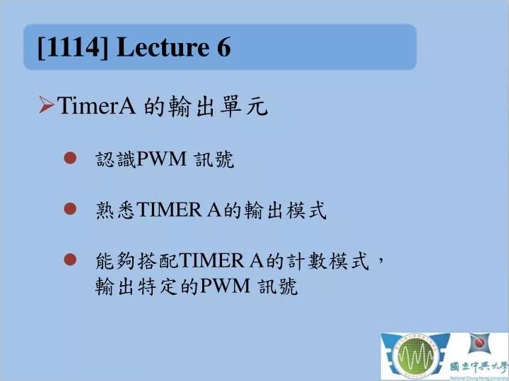
[1114] Lecture 6. TimerA 的 輸出單元 認識 PWM 訊號 熟悉 TIMER A 的輸出模式 能夠搭配 TIMER A 的計數模式, 輸出特定的 PWM 訊號. Review. Timer A0 模組 Timer A0 模組提供 五組 CCR 模組,提供比較、抓取、和輸出的功能 Timer A 模組共有三種計數模式,分別為 Up Mode 、 Continuous Mode 和 Up/Down 模式 Up Mode 和 Up/Down Mode 皆以 TA0CCR0 的值為上限,需先設定。. Review.

E N D
[1114]Lecture 6 • TimerA的輸出單元 • 認識PWM 訊號 • 熟悉TIMERA的輸出模式 • 能夠搭配TIMERA的計數模式,輸出特定的PWM 訊號
Review • Timer A0 模組 • Timer A0模組提供 五組CCR 模組,提供比較、抓取、和輸出的功能 • Timer A模組共有三種計數模式,分別為UpMode、Continuous Mode 和Up/Down 模式 • Up Mode 和Up/Down Mode 皆以TA0CCR0的值為上限,需先設定。
Review • Timer A 模組 • 使用Timer A需要設定TA0CTL 暫存器,以及有使用到的TA0CCTLx 暫存器 • TIMER A 模組內含的計數暫存器有:TA0RTA0CCR0~TA0CCR4.
PWM • PWM 訊號 • 是一種方波訊號 • 廣泛得被應用於各種裝置 • PWM 訊號有兩種參數:一個是PWM的頻率,一個是PWM的Duty cycle。
TimerA • TimerA的輸出單元 • 以TA0為例,TA0的每一個CCRx模組都可以提供一個輸出,為TA0.x。 • 由電路圖可以找到每個CCRx模組的輸出腳位
TimerA • 使用TimerA的輸出模組 • TAxCTL設定
TimerA • 使用TimerA的輸出單元 • 設定TAxCCTLn,以TA0CCR1輸出為例,則設定TA0CCTL1。
TimerA • TIMERA的輸出模式: • Mode 0: OUT根據TA0CCTL1.2 (OUT bit) 輸出準位,準位會隨著OUT bit的值隨時改變。 • Mode 1: Set在SET 模式中,起始值為LOW,第一次EQU1出現後設值為HIGH,並且不再改變直到Timer 被重置。EQU1 意謂 TA0R EQUALs to TA0CCR1.
TimerA • TIMERA的輸出模式: • Mode 2 : Toggle/RESET在TOGGLE/RESET模式中,輸出準位會在TA0R數到EQU1時toggle,並且在TA0R數到EQU0時重置為LOW。 • Mode 3: Set/Reset在此模式中,輸出準位會在EQU1時設定為HIGH,在EQU0時設定為LOW。
TimerA • TIMERA的輸出模式: • Mode 4 : Toggle在此模式中,輸出準位會在EQU1時Toggle。特色為PWM週期為Timer周期的兩倍(Up/Down Counting 除外)。 • Mode 5: Reset輸出準位在EQU1時設為LOW,直到被設定為其他的OUTPUTMODE並佈署到輸出。
TimerA • TIMERA的輸出模式: • Mode 6 : Toggle/Set輸出準位在EQU1時切換狀態,並且在EQU0時設定為1。 • Mode 7: Reset/Set輸出準位在EQU1時設為LOW,EQU0時設定為1。
TimerA • TimerA0各計數模式下的輸出行為: • UPMode,上數到TA0CCR0的值,計數週期是 • Continuous Mode,上數到FFFFx,計數週期為 • Up/Down Mode,上數到TA0CCR0,再下數到0,計數週期為。
TimerA • Up Mode中的計數模式 • Mode2:f = ,duty cycle = • Mode3:f = ,duty cycle =
TimerA • Up Mode中的計數模式 • Mode4:f = ,duty cycle = • Mode6:f = ,duty cycle = • Mode7:f = ,duty cycle =
TimerA • Continuous中的計數模式 • Mode2:f = ,duty cycle = • Mode3:f = ,duty cycle =
TimerA • Continuous中的計數模式 • Mode4:f = ,duty cycle = • Mode6:f = ,duty cycle =
TimerA • Continuous中的計數模式 • Mode7:f = ,duty cycle =
TimerA • Up/Down Mode中的計數模式 • Mode2:f = ,duty cycle = • Mode3:f = ,duty cycle =
TimerA • Up/Down中的計數模式 • Mode4:f = ,duty cycle = • Mode6:f = ,duty cycle =
TimerA • Up/Down中的計數模式 • Mode7:f =,duty cycle =
TimerA • 實作步驟: 以TA0.1輸出 • WDTCTL 設定 • TA0CTL 設定時脈與計數模式 • 設值TA0CCR0 • TA0CCTL1設定輸出模式 • 設值TA0CCR1
TimerA • 實作步驟: 以TA0.1輸出 • 查詢輸出腳位 • 以P1DIR 打開 對應腳位輸出 • 以P1SEL 選擇腳位功能P1SEL.x=0:P1.xP1SEL.x = 1: Other function.
TimerA • 實作範例 • 範例6 • Up Mode 計數模式 • Mode6 toggle/Set • 20Hz; 40% duty cycle • TA0.1輸出
TimerA • 練習1: • 以TA0.1輸出一個20Hz,Duty cycle為50%的PWM 訊號,計數模式選用Up mode。
TimerA • 練習2: • 以TA0.1輸出,計數模式不拘,以按鍵中斷控制PWM的Duty cycle約為20%, 40%, 60%, 80%.
[1114]Lecture 6 • 完成後,找到專案裡面的source file,以附檔形式寄到 kchu@ares.ee.nchu.edu.tw,並在主旨中註明姓名、系級與學號,source檔名稱請利於辨識。EX: • 主旨: 微處理機實習 LAB3 胡國治 電機碩二 7101064123