Triplet correctors specifications
This document outlines the specifications and impact of triplet correctors used in the LHC to mitigate non-linear errors affecting dynamic aperture. It discusses strategies for optimizing the strength of dipole correctors, including options for mitigating transverse misalignments and systematic errors. The evolution of corrector placement and design for the HL-LHC project is highlighted, along with numerical simulations assessing the effect of non-linear correctors on dynamic aperture. Overall, the findings support improved particle beam trajectory stability.

Triplet correctors specifications
E N D
Presentation Transcript
Triplet correctors specifications Massimo Giovannozzi , Stéphane Fartoukh, Riccardo de Maria – CERN Acknowledgements: Ezio Todesco
Outline Introduction Dipole correctors Impact of non-linear correctors on dynamic aperture Strength specification of correctors Summary and outlook
Outline Introduction Dipole correctors Impact of non-linear correctors on dynamic aperture Strength specification of correctors Summary and outlook
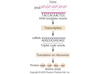
Introduction - I • Situation in nominal LHC: • Non-linear corrector package provides compensation for non-linear errors in the IR (triplets, D1, D2). • Location of the correctors changed between V6.4 and V6.5 to provide more favourable optical conditions.
Introduction - II • Strategy to set the correctors’ strength (see S. Fartoukh, LHC Project Note 349): minimisation of driving terms. • Selection of the driving terms to be corrected: • b3: c(b3; 1, 2) and c(b3; 2, 1) • a3: c(a3; 0, 3) and c(a3; 3, 0) • b4: c(b4; 4, 0) and c(b4; 0, 4) • a4: c(a4; 3, 1) and c(a4; 1, 3) • b6: c(b6; 0, 6) and c(b6; 6, 0) The choice of the resonances is based on the proximity to the working point Feed down effects are not included in the correction strategy, but effect from systematic errors is minimised.
Introduction - III • What is new in HL-LHC: • The D1 separation magnet is cold and its field quality will contribute to the strength requirement of the triplets’ correctors. • Additional corrector magnets have been requested: b5, a5, a6. • Strategy to set these additional correctors: • a5: c(a5; 0, 5) and c(a5; 5, 0) • b5: c(b5; 5, 0) and c(b5; 0, 5) • a6: c(a6; 5, 1) and c(a6; 1, 5)
Introduction - IV • Proposed layout: • Dipole orbit correctors: Q2a, Q2b, Corrector Package, D2 • Higher-order: Corrector Package Conceptual layout derived from Phase I layout, but with additional magnets in the corrector package.
Outline Introduction Dipole correctors Impact of non-linear correctors on dynamic aperture Strength specification of correctors Summary and outlook
Dipole correctors - I See talk by M. Fitter for additional studies • Three nested-dipole correctors are planned for the new IT: • MCBX1 and MCBX2: installed on IP-side of Q2a and on non-IP side of Q2b. Their length is 1.3 m. • MCBX3: has a strength that is roughly double the one of MCBX1/2 for a length of 2 m. • The requirements on the MCBX strength have been specified based on • The crossing angle reach • The need for the correction of transverse misalignments of the IT • The need to cope with strength errors in the quadrupole magnets. • MCBX1, 3 and MCBRD are used to generate the crossing angle and require 0.4 Tm, 2.1 Tm, 4.6 Tm for 590 rad at 7 TeV, and a parallel separation of 1.5 mm, respectively. • Monte Carlo simulations were performed assuming a maximum IT misalignment of ±0.5 mm. • Using an 8-corrector scheme (also called short-range scheme), one needs 1.2 Tm for MCBX1/3, 2 Tm for MCBX2 and 0.1 Tm for the MCBRD, and the peak residual orbit is 0.5 mm. • A 10-corrector scheme (also called long-range scheme) reduces the integrated strength requirements to 0.8 Tm for MCBX1,2,3 but increases the MCBRD strength up to 0.4 Tm and the peak residual orbit can reach 1.4 mm.
Dipole correctors - II Integrated strength distribution of the proposed orbit correctors for the short- (left) and long-range (right) scheme correction of ±0.5 mm IT transverse misalignment. Residual closed orbit in the IT as a function of the correction strategy selected. The short-range approach minimisesresidual orbit, but requires a much larger strength.
Dipole correctors - III Summary of integrated strength requirements for various scenarios Orbit correction: ±0.5 mm misalignment. Crossing angle: 720 mrad Operational margins: parallel separation, IP shift, VdM scans… Triplets’ correctors D2 corrector
Outline Introduction Dipole correctors Impact of non-linear correctors on dynamic aperture Strength specification of correctors Summary and outlook
Impact of non-linear correctors on DA - I • The so-called SLHCV3.1b layout, with a triplet gradient of 150 T/m, has been used and several configurations considered: • With or without the full correction system • With one single corrector not used • With an intermediate configuration in which the correctors corresponding to a5, b5, a6are not used. • Setting up of numerical simulations: • 59 phase space angles • 60 seeds • 105 turns • The field errors are assigned to all magnets in the arcs and IRs based on the data of the magnetic measurements.
Impact of non-linear correctors on DA - II Markers: average DA over seeds and angles Negative error bars: minimum DA over seeds and angles Positive error bars: average DA over angles of the maximum over seeds. Left plot: DAave affected by b6, but DAmin also by low order correctors. Right plot: for complete non-linear correction system ~ 5 σ gained for DAaveand DAmin. a5,b5,a6correctors increase DAaveby 1.5 σ and DAminby more than 3 σ.
Outline Introduction New layout of correctors Impact of non-linear correctors on dynamic aperture Strength specification of correctors Summary and outlook
Strength specification of correctors - I • Checked the distribution of strengths for the usual 60 realisations of the multipole errors in triplets and D1. • Data from IR1/5, left and right side of IRs have been combined. • Error tables used: • Triplets: optimised (by tracking simulations) error table based on November 6 2012 table provided by WP3 (E. Todesco). • D1: November 6 2012 table provided by WP3 (E. Todesco). • For the specification of the a2 corrector, 20 units of random a2 to simulate a maximum roll angle of 3 mrad (1mrad rms) has been added to the target errors (uniform random distribution).
Strength specification of correctors - II Error tables used: The values are in units of 10−4 at Rref=50 mm To note the difference between b6 and a6
Strength specification of correctors - III The impact of the difference between b6 and a6
Strength specification of correctors - IV Strength distribution of the skew quadrupole corrector
Strength specification of correctors - V Final specification table: Upper bound for correctors’ strength from simulations Specification: added a safety factor 1.5-2 with respect to simulations
Summary and outlook - I • An effective non-linear correctors’ system has been devised for the HL-LHC machine. The detailed specification of the layout and strength of the correctors has been given. • A specification document has been prepared (HiLumi-Mil-M24_28). • The dipole correctors will be further studied to assess whether their strength is optimal for ensuring the performance reach of HL-LHC. In particular: • Tests of orbit correction performance under different conditions, including margins for IP displacement. • Assessment of required optics flexibility as it impacts on the performance of the orbit correctors. • Important point: as a next step, the official HLLHCV1.0 layout with be used to probe the situation in terms of correctors effectiveness and performance need. Some improvements are expected and they will be reflected in revised integrated strength specifications.
Summary and outlook - II • Given the results about D2 expected field quality (see presentation by Y. Nosochkov et al.) in the future we might explore: • The possibility to use the correctors to compensate also for the field quality of the D2 separation dipoles. • The possibility to use a corrector package for D2.