Download
1 / 24
260 likes | 497 Views
CHAPTER 1 TYPES OF ENGINES. Internal Combustion Engine. The internal combustion engine is an engine in which the combustion of a fuel (normally a fossil fuel) occurs with an oxidizer (usually air) in a combustion chamber. 2 – Stroke Engine. Rotay Engine. 4 – Stroke Engine.

E N D
Internal Combustion Engine The internal combustion engine is an engine in which the combustion of a fuel (normally a fossil fuel) occurs with an oxidizer (usually air) in a combustion chamber. 2 – Stroke Engine Rotay Engine 4 – Stroke Engine
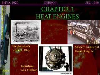
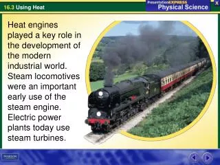
External Combustion Engine An external combustion engine (EC engine) is a heat engine where an (internal) working fluid is heated by combustion in an external source, through the engine wall or a heat exchanger. The fluid then, by expanding and acting on the mechanism of the engine, produces motion and usable work.The fluid is then cooled, compressed and reused (closed cycle), or (less commonly) dumped, and cool fluid pulled in (open cycle air engine). Jet Engine Lokomotif engine
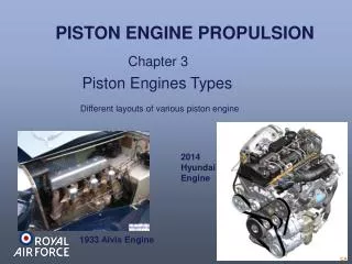
INTERNAL COMBUSTION ENGINE () Reciprocating Engine A reciprocating engine, also often known as a piston engine, is a heat engine that uses one or more reciprocating pistons to convert pressure into a rotating motion. This article describes the common features of all types. The main types are: the internal combustion engine, used extensively in motor vehicles; the steam engine, the mainstay of the Industrial Revolution; and the niche application Stirling engine. Stirling Engine 4 Stroke Engine 2 Stroke Engine
Rotary Engine A rotary engine is essentially a standard Otto cycle engine, but instead of having a fixed cylinder block with rotating crankshaft as with a conventional radial engine, the crankshaft remains stationary and the entire cylinder block rotates around it. In the most common form, the crankshaft was fixed solidly to an aircraft frame, and the propeller simply bolted onto the front of the crankcase.
2 Stroke Spark Ignition Engine A two-stroke engine is an internal combustion engine that completes the process cycle in one revolution of the crankshaft (an up stroke and a down stroke of the piston, compared to twice that number for a four-stroke engine). This is accomplished by using the end of the combustion stroke and the beginning of the compression stroke to perform simultaneously the intake and exhaust (or scavenging) functions. In this way, two-stroke engines often provide high specific power, at least in a narrow range of rotational speeds. The functions of some or all of the valves required by a four-stroke engine are usually served in a two-stroke engine by ports that are opened and closed by the motion of the piston(s), greatly reducing the number of moving parts.
Working Priciple of 2 Stroke Spark Ignition Engine Intake The fuel/air mixture is first drawn into the crankcase by the vacuum that is created during the upward stroke of the piston. The illustrated engine features a poppet intake valve; however, many engines use a rotary value incorporated into the crankshaft. Crankcase compression During the downward stroke, the poppet valve is forced closed by the increased crankcase pressure. The fuel mixture is then compressed in the crankcase during the remainder of the stroke.
Transfer/Exhaust Toward the end of the stroke, the piston exposes the intake port, allowing the compressed fuel/air mixture in the crankcase to escape around the piston into the main cylinder. This expels the exhaust gasses out the exhaust port, usually located on the opposite side of the cylinder. Unfortunately, some of the fresh fuel mixture is usually expelled as well. Compression The piston then rises, driven by flywheel momentum, and compresses the fuel mixture. (At the same time, another intake stroke is happening beneath the piston). Power At the top of the stroke, the spark plug ignites the fuel mixture. The burning fuel expands, driving the piston downward, to complete the cycle. (At the same time, another crankcase compression stroke is happening beneath the piston.)
2 Stroke Spark Ignition Figure 2 Stroke Spark Ignition Animation
4 Stroke Spark Ignition Engine A four-stroke engine, also known as four-cycle, is an internal combustion engine in which the piston completes four separate strokes—intake, compression, power, and exhaust—during two separate revolutions of the engine's crankshaft, and one single thermodynamic cycle. Working Priciple of 4 Stroke Spark Ignition Engine INTAKE stroke: on the intake or induction stroke of the piston, the piston descends from the top of the cylinder to the bottom of the cylinder, reducing the pressure inside the cylinder. A mixture of fuel and air, or just air in a diesel engine, is forced by atmospheric (or greater) pressure into the cylinder through the intake port. The intake valve(s) then close. The volume of air/fuel mixture that is drawn into the cylinder, relative to the volume of the cylinder is called, the volumetric efficiency of the engine.
COMPRESSION stroke: with both intake and exhaust valves closed, the piston returns to the top of the cylinder compressing the air, or fuel-air mixture into the combustion chamber of the cylinder head. POWER stroke: this is the start of the second revolution of the engine. While the piston is close to Top Dead Center, the compressed air–fuel mixture in a gasoline engine is ignited, usually by a spark plug, or fuel is injected into the diesel engine, which ignites due to the heat generated in the air during the compression stroke. The resulting massive pressure from the combustion of the compressed fuel-air mixture forces the piston back down toward bottom dead centre. EXHAUST stroke: during the exhaust stroke, the piston once again returns to top dead center while the exhaust valve is open. This action evacuates the burnt products of combustion from the cylinder by expelling the spent fuel-air mixture out through the exhaust valve(s).
1st Stroke = INTAKE stroke = 180° of crankshaft revolution Top Dead Centre (TDC) 4th Stroke = INTAKE stroke = 720° of crankshaft revolution 2nd Stroke = INTAKE stroke = 360° of crankshaft revolution Bottom Dead Centre (BDC) 3rd Stroke = INTAKE stroke = 540° of crankshaft revolution
4 Stroke Compression Ignition Engine In compression ignition (CI) engines, burning of fuel occurs due to compression of the fuel to very high pressures. At very high pressures the fuel, i.e. diesel, starts burning automatically without the need of any external flame. The cycle of operation of the CI engine is completed in four-strokes: suction, compression, expansion, and exhaust A four stroke CI engine consists of the following four strokes. 1.Suction or Intake stroke 2.Compression Stroke 3.Expansion or power stroke 4. Exhaust stroke
1. Suction Stroke: This stroke starts when the piston is at the top dead centre. When it moves downwards it will create suction and only air enters the cylinder. The inlet valve is open at this time and exhaust valve is closed. When the piston reaches at the bottom dead centre the inlet valve closes and the suction stroke ends. It all takes place in 180º of the crankshaft rotation. 2. Compression stroke: In this stroke the piston starts moving upward. During this stroke both the inlet and exhaust valves are closed. The air is compressed by the upward movement of the piston. At the end of the compression stroke the fuel is injected into the combustion chamber. An injector is provided to inject the fuel. At the end of compression stroke the temperature is sufficient to ignite the fuel and the combustion of fuel-air mixture takes place. 3. Expansion or Power Stroke: Due to the high pressure of the burnt gases the piston moves towards bottom dead centre. Both the inlet and exhaust valve remains closed during the stroke.
4. Exhaust stroke: When the piston is at the bottom dead centre the exhaust valve opens. As the pressure falls to atmospheric level. The piston moves from Top dead centre to bottom dead centre and sweeps the products of discharge out at nearly atmospheric pressure. The exhaust valve closes at the end of exhaust stroke. The gases are not fully exhausted. Some of the burnt gases stills remains in the clearance volume. The engine in which the cycle of operations is completed in two revolutions (720º) of the crank shaft or four strokes of the piston is known as the four stroke engine. One stroke is completed when the piston moves from Top dead centre to Bottom Dead Centre or when the crank rotates through 180º. In four stroke CI engine the combustion of fuel-air mixture takes place with compression. The engine operates at a high compression ratio of the order of 16 to 20. Due to high compression ratio the mixtures reaches its ignition temperature and the combustion takes place.
Schematic Diagram for Compression Ignition (CI) @ Diesel Engine Process
Rotary (Wankel)Engine Principles of a Rotary Engine Like a piston engine, the rotary engine uses the pressure created when a combination of air and fuel is burned. In a piston engine, that pressure is contained in the cylinders and forces pistons to move back and forth. The connecting rods and crankshaft convert the reciprocating motion of the pistons into rotational motion that can be used to power a car. In a rotary engine, the pressure of combustion is contained in a chamber formed by part of the housing and sealed in by one face of the triangular rotor, which is what the engine uses instead of pistons.
The rotor follows a path that looks like something you'd create with a Spirograph. This path keeps each of the three peaks of the rotor in contact with the housing, creating three separate volumes of gas. As the rotor moves around the chamber, each of the three volumes of gas alternately expands and contracts. It is this expansion and contraction that draws air and fuel into the engine, compresses it and makes useful power as the gases expand, and then expels the exhaust.
Parts of Rotary Engine Housing Rotor Output Shaft
Gas Turbine engine A gas turbine, also called a combustion turbine, is a type of internal combustion engine. It has an upstream rotating compressor coupled to a downstream turbine, and a combustion chamber in-between. Energy is added to the gas stream in the combustor, where fuel is mixed with air and ignited. In the high pressure environment of the combustor, combustion of the fuel increases the temperature. The products of the combustion are forced into the turbine section. There, the high velocity and volume of the gas flow is directed through a nozzle over the turbine's blades, spinning the turbine which powers the compressor and, for some turbines, drives their mechanical output. The energy given up to the turbine comes from the reduction in the temperature and pressure of the exhaust gas.
Gas turbine engines are, theoretically, extremely simple. They have three parts: Compressor - Compresses the incoming air to high pressure Combustion area - Burns the fuel and produces high-pressure, high-velocity gas Turbine - Extracts the energy from the high-pressure, high-velocity gas flowing from the combustion chamber Compressor Combustion area Turbine
Power-to-weight ratio Power-to-weight ratio (or specific power or power-to-mass ratio) is a calculation commonly applied to engines and mobile power sources to enable the comparison of one unit or design to another. Power-to-weight ratio is a measurement of actual performance of any engine or power sources. It is also used as a measurement of performance of a vehicle as a whole, with the engine's power output being divided by the weight (or mass) of the vehicle, to give a metric that is independent of the vehicle's size. Power-to-weight is often quoted by manufacturers at the peak value, but the actual value may vary in use and variations will affect performance. The inverse of power-to-weight, weight-to-power ratio (power loading) is a calculation commonly applied to aircraft, cars, and vehicles in general, to enable the comparison of one vehicle performance to another. Power-to-weight ratio is equal to powered acceleration multiplied by the velocity of any vehicle.
The power-to-weight ratio (Specific Power) formula for an engine (power plant) is the power generated by the engine divided by weight of the engine as follows: Example: Please calculate the power to weight ratio as given data. A typical turbocharged V8 diesel engine might have an engine power of 330 horsepower (250 kW) and a weight of 835 pounds (379 kg),[1] giving it a power-to-weight ratio of 0.65 kW/kg (0.40 hp/lb).