Download
1 / 24
270 likes | 555 Views
PTT 201/4 THERMODYNAMICS SEM 1 ( 2013/2014). CHAPTER 11: Refrigeration Cycles . Objectives. Introduce the concepts of refrigerators and heat pumps and the measure of their performance. Analyze the ideal vapor-compression refrigeration cycle.

E N D
PTT 201/4THERMODYNAMICS SEM 1 (2013/2014) CHAPTER 11: Refrigeration Cycles
Objectives • Introduce the concepts of refrigerators and heat pumps and the measure of their performance. • Analyze the ideal vapor-compression refrigeration cycle. • Analyze the actual vapor-compression refrigeration cycle. • Review the factors involved in selecting the right refrigerant for an application.
REFRIGERATORS The transfer of heat from a low-temperature region to a high-temperature one requires special devices called refrigerators. Refrigerators are cyclic device, and the working fluids used in the refrigeration cycles are called refrigerants.
HEAT PUMPS Another device that transfers heat from a low-temperature medium to ahigh-temperature one is the heat pump. Refrigerators and heat pumps are essentially the same devices; they differ in their objectives only.
REFRIGERATORS AND HEAT PUMPS -The objective of a refrigerator is to remove heat (QL) from the cold medium. -The objective of a heat pump is to supply heat (QH) to a warm medium. for fixed values of QL and QH
The cooling capacity of a refrigeration system – is the rate of heat removal from the refrigeration space – is often expressed in terms of ton of refrigeration. The capacity of a refrigeration system that can freeze 1 ton of liquid water at 0 °C into ice at 0 °C in 24 h is said to be 1 ton.
VAPOR-COMPRESSION REFRIGERATION CYCLE Two modes of operations: Ideal vapor-compression refrigeration cycle Actual vapor-compression refrigeration cycle
THE IDEAL VAPOR-COMPRESSION REFRIGERATION CYCLE The vapor-compression refrigeration cycle is the ideal model for refrigeration systems, air conditions and heat pumps. It consist of four processes: 1-2 Isentropic compression in compressor. 2-3 Constant-pressure heat rejection in a condenser. 3-4 Throttling in an expansion devise. 4-1 Constant-pressure heat absorption in an evaporator.
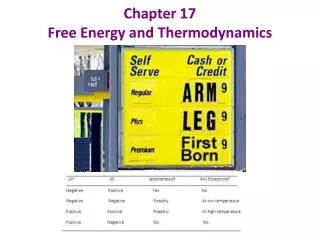
THE IDEAL VAPOR-COMPRESSION REFRIGERATION CYCLE Schematic and T-s diagram for the ideal vapor-compression refrigeration cycle.
THE IDEAL VAPOR-COMPRESSION REFRIGERATION CYCLE The process in ideal vapor compression refrigeration cycle: The refrigerant enters the compressor at state 1 as saturated vapor and is compressed isentropically to the condenser pressure. The temperature of the refrigerant increases during this isentropic compression process to well above the temperature of the surrounding medium. The refrigerant then enters the condenser as superheat vapor at state 2 and leaves as saturated liquid at state 3 as a result to the heat rejection to the surrounding. The saturated liquid at state 3 enters an expansion valve or capillary tube and leaves at evaporator pressure. The temperature of refrigerant drop below the temperature of refrigerated space during this stage. The refrigerant enters the evaporator at stage 4 as saturated mixture and it completely evaporate by absorbing the heat from the refrigerated space. The refrigerant leaves the evaporator as saturated vapor and reenters the compressor, completing the cycle.
THE IDEAL VAPOR-COMPRESSION REFRIGERATION CYCLE The area under the curve for the process 4-1 represents the heat absorbed from the refrigeration space. Area under the curve 2-3 represented the heat rejected to the surrounding. COP improves by 2-4% for each compressor ifthe evaporating temperature is raised or the condensing temperature is lowered.
THE IDEAL VAPOR-COMPRESSION REFRIGERATION CYCLE process curve 4’-4 in fig 11-3) and the net work input would decrease (by the amount of work output of the turbine). Replacing the expansion valve by the turbine is not practical, since the added benefits cannot justify the added cost and complexity
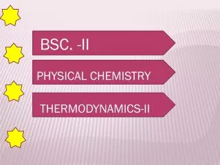
Steady-flow energy balance The P-h diagram of an ideal vapor-compression refrigeration cycle.
Sat Vapor Superheated Sat Liquid Throttling
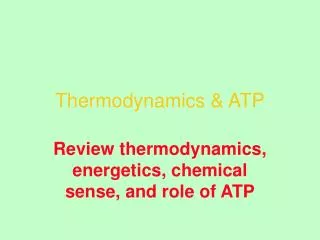
ACTUAL VAPOR-COMPRESSION REFRIGERATION CYCLE An actual vapor-compression refrigeration cycle differs from the ideal one owing mostly to the irreversibilities that occur in various components, mainly due to fluidfriction (causes pressure drops) and heat transfer to or from the surroundings. The COP decreases as a result of irreversibilities. DIFFERENCES Non-isentropic compression Superheated vapor at evaporator exit Subcooled liquid at condenser exit Pressure drops in condenser and evaporator Schematic and T-s diagram for the actual vapor-compression refrigeration cycle.
Example: • Refrigerant-134a enters the compressor of refrigerator as superheated vapor at 0.14 Mpa and -10 C at a rate of 0.05 kg/s and leaves at 0.8 Mpa and 50 C. The refrigerant is cooled in the condenser to 26 C and 0.72 Mpa and is throttled to 0.15 Mpa. Disregarding and heat transfer and pressure drops in the connecting lines between the components, determine: • The rate of heat removal from the refrigerated space and the power input to the compressor. • The isentropic efficiency of the compressor. • The coefficient of performance of refrigerator. Superheated Superheated Sat Liquid Throttling
SELECTING THE RIGHT REFRIGERANT • Several refrigerants may be used in refrigeration systems such as chlorofluorocarbons (CFCs), ammonia, hydrocarbons (propane, ethane, ethylene, etc.), carbon dioxide, air (in the air-conditioning of aircraft), and even water (in applications above the freezing point). • R-11, R-12, R-22, R-134a, and R-502 account for over 90 percent of the market. • The industrial and heavy-commercial sectors use ammonia (it is toxic). • R-11 is used in large-capacity water chillers serving A-C systems in buildings. • R-134a (replaced R-12, which damages ozone layer) is used in domestic refrigerators and freezers, as well as automotive air conditioners. • R-22 is used in window air conditioners, heat pumps, air conditioners of commercial buildings, and large industrial refrigeration systems, and offers strong competition to ammonia. • R-502 (a blend of R-115 and R-22) is the dominant refrigerant used in commercial refrigeration systems such as those in supermarkets. • CFCs allow more ultraviolet radiation into the earth’s atmosphere by destroying the protective ozone layer and thus contributing to the greenhouse effect that causes global warming. Fully halogenated CFCs (such as R-11, R-12, and R-115) do the most damage to the ozone layer. Refrigerants that are friendly to the ozone layer have been developed. • Two important parameters that need to be considered in the selection of a refrigerant are the temperatures of the two media (the refrigerated space and the environment) with which the refrigerant exchanges heat.