Download
1 / 36
360 likes | 401 Views
Learn about the TAC Project in Turkey, including its development timeline, facilities, collaborations, and planned accelerator applications in physics research. Discover the key features of TAC's particle factory, synchrotron radiation facility, and SASE FEL facility.

E N D
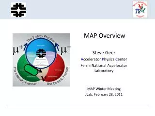
TURKISHACCELERATORCENTER (TAC) IR FEL AND BREMSSTRAHLUNG PROJECT http://thm.ankara.edu.tr V. Avrasya Nükleer Bilimler Konferansı 14-17 Ekim 2008, TAEK, Ankara, TÜRKİYE Ö. Yavaş, A. Aksoy, B. Kenetoğlu, Ö. Karslı, Y. Moğulkoç, S. Tekin, M. Tural Ankara University TAEK, Ankara
Contents • Introduction • Short Chronology of TAC Project • Contents of TAC Project • IRFEL & Bremsstrahlung (First Facility) • Time Schedule of TAC • Conclusion TAEK, Ankara
Short chronology of the TAC Project Approximately 10 years ago, linac-ring type charm-tau factory with synchrotron light source was proposed as a regional project for elementary particle physics. S. Sultansoy, Turk. J. Phys. 17 (1993) 591; Turk. J. Phys. 19 (1995) 785. Starting from 1997, a small group from Ankara and Gazi Universities begins afeasibility study for the possible accelerator center in Turkey with the support of Turkish State Planning Organization (DPT). http://thm.ankara.edu.tr TAEK, Ankara
The results of the study are published in A. K. Çiftçi et al., Turk. J. Phys. 24 (2000) 747 and presented at EPACs Ö. Yavaş, A. K. Çiftçi, S. Sultansoy, EPAC 2000, p. 1008. A. K. Çiftçi et al., EPAC 2002, p. 1100. Ö. Yavaş et al., EPAC 2006 Starting from 2002, the conceptual design study of the TAC project has started with a relatively enlarged group (again with the DPT support). The results are published in S. Sultansoy et al., PAC 2005 Short chronology of the TAC Project TAEK, Ankara 4
TAC Project includes First Facility: IR FEL & Brems. (06-10) SASE FEL based on electron linac(Eelectron=1 GeV) Synchrotron light source based on positron ring (Epositron=3.5 GeV) Linac-ring type electron-positron collider (particle (charm) factory) (Ec.m.= 3.77 GeV) GeV scale proton accelerator (Eproton= 1-3 GeV) (linac or Synchrotron) TAEK, Ankara 5
I. Step: Feasibility Report for TAC (1997-2000) II. Step: Conceptual Design Report (CDR) of TAC (2002-2005) III. Step: - Technical Design Report (TDR) of TAC - Pilot Facility (IR FEL & Brems.) - Institute of Accelerator Technologies (2006-2011) IV. Step: Completion of TAC (2012-2022) Short chronology of the TAC project TAEK, Ankara 6
National Collaboration In 2006, 10 Turkish Universities with 70 researchers collaborated in order to write Techinal Design Report (TDR) and to construct first facility (IR FEL Facility) of TAC. Ankara University (Coordinator) Boğaziçi University Gazi University Doğuş University İstanbul University Erciyes University Uludağ University Süleyman Demirel University Dumlupınar University Niğde University TAEK, Ankara 7
International Collaborations • CERN (Geneva) 08/2005 – 08/2009 • DESY (Hamburg) 03/2007 – 12/2011 • BESSY (Berlin) 03/2007 – 12/2011 • FZD (Dresden) 01/2007 – 12/2011 • 4GLS (Daresbury) • iFEL (Osaka Univ.) • John Adams Inst. (Oxford Univ.) • ELETTRA (Trieste) TAEK, Ankara 8
TURKISH ACCELERATOR CENTER (TAC) PROJECT • TAC will include: • 1 GeV electron linac • 3.56 GeV positron ring • 1 - 3 GeV proton linac TAEK, Ankara 9
MAIN FOUR FACILITIES OF TAC 1 Particle Factory (Charm Factory) 2 3rd Generation Synchrotron Radiation based on 3.5 GeV Positron Ring 3 SASE FEL based on 1 GeV e- linac 4 1-3 GeV Proton Accelerator TAEK, Ankara 10
TAC Particle (Charm) Factory It is planned to collide the electrons coming through the linac with an energy of 1GeV with the positrons coming from the synchrotron with an energy of 3.56 GeV. It is aimed to produce charm particle with a center of mass energy 3.77 GeV. ( ) TAEK, Ankara 11
Tentative parameters of TAC charm factory TAEK, Ankara 12
Synchrotron Radiation (SR) Facility Main parameters of TAC SRFacility were reported at EPAC 2000 [6]. • It was planned to obtain a third generation light source “Synchrotron Radiation” from the positron ring with energy of 3.5 GeV. TAEK, Ankara 13
Self Amplified Spontaneous EmissionFree Electron Laser (SASE FEL) A SASE FEL facility is also planned as a 4th generation ligth source in the frame ofTAC. Such a facility may be based on 1 GeV electron linac of the collideror a special independent linac. As an alternative, electron accelerator whichwill drive SASE FEL, energy recovery linac (ERL) can be proposed. TAEK, Ankara 14
1 GeV electron beam, undulator and SASE FEL parameters TAEK, Ankara 15
Proton Accelerator (PA) Facility • TAC proton accelerator proposal consists of 100-300 MeV energy linear pre-accelerator and 1-3 GeV main linac. • The average beam current values for these machines would be ~30 mA and ~0.3 mA, respectively. • Proton beams from two different points of the synchrotron will be forwarded to neutron and muonregions, where a wide spectrum of applied research is planned. In addition, some Accelerator Driven System (ADS) applications are planned. TAEK, Ankara 16
Planned uses of proton accelerator • Muon region • fundamental investigations • test of QED and • muonium-antimuonium oscillations... • applied investigations with SR method • High-Tc superconductivity • phase transitions • impurities in semiconductors... • Neutron region • applied physics • molecular biology • fundamental physics TAEK, Ankara 17
THE FIRST FACILITY OF TAC: IRFEL & BREMSSTRAHLUNG • Indeed, the main aims of first facility: • to get experience on accelerator technology on • smaller scale • - to make research by using accelerators • - to train accelerator physicists • We are planning to build the facility (IR FEL&Brems.) until 2011 in Ankara University Campus at Gölbaşı, Ankara. TAEK, Ankara
The Place of TAC IR-FEL TAC IR FEL TAEK, Ankara 19
Sc Linac Option: • TAC IR FEL will be an oscillator FEL and include • a linac to get an electron beamin 15-40 MeV energy range and two optical resonators with two undulators that will produce laser at wavelength range of 2-180 μm. 16 kW klystrons are considered to obtain the essential beam power. IR FEL thought to work in oscillator mode. TAEK, Ankara 20
Sc Linac Option: • Main parameters of electron beam TAEK, Ankara 21
Sc Linac Option: TAEK, Ankara 22
Parameters of Undulator Magnets and Free Electron Laser (FEL) TAEK, Ankara 23
Bremsstrahlung Facility of TAC Also, a Bremsstrahlung beam line and experimental stations for nuclear physics studies are planned for TAC. The energy spectrum of photons due tobremsstrahlung of electrons decelerated in the electric field of atomic nuclei dependson the energy levels of the atomic electrons, due to the screening effect they haveon the moving particle, and on the particle velocity. The spectrum extends up toquanta of the energy of the moving particle. It is important to extract electron beam of 20 MeVenergy from LINAC and sent it to the Bremsstrahlung experimental hall. Main aimof Bremsstrahlung station is to study nuclear spectroscopy. TAEK, Ankara 24
Experiments with Bremsstrahlung Electron beam of the superconducting linear accelerator with a maximum electron energy of 20 MeV. The bremsstrahlung photons are used to irradiate the target which is made of the isotope to be investigated. Nuclei of the target material may then be excited by the photons and emit characteristic γ rays. A simplified picture of this process is shown in the figure. For example, the neutrons in a deformed nucleus may oscillate against the protons, which causes magnetic dipole (M1) radiation (upper part). If in a nucleus with a neutron excess the neutrons vibrate against the protons, then electric dipole (E1) radiation is emitted (lower part). TAEK, Ankara 25
B. NcLinacOption: • Due to some technological hardnesses like cryogenics and total budget issues for Sctechnology, we are looking for Nc linac option, also. • Some technical descriptions of designed Nc linac structure • are given as following: • - 90 keV electron gun • - 3 GHz injector system • 15-50 MeV linac structure with 3 GHz RF cavities • Design studies of 15-50 MeV Nc linac were made by ACCEL Co. of Germany. TAEK, Ankara 26
B. NcLinacOption: Main parameters of Nc linac TAEK, Ankara 27
Infrared spectroscopy Infrared microscopy Infrared imaging Material science Semiconductors Photochemistry Impurities Elipsometry THz spectroscopy Photo-thermal spectroscopy Photo-acustic spectroscopy Sum frequency spectroscopy Near field optical microscopy Pumb-prob measurements Vibrational and rotational spectroscopy Characterization of molecular structures Application fields of Infrared FEL (IR FEL): • Structural changes in DNA • Protein dynamics • Nonlinear optics • Quantum dots • Super lattices • Photo-chemistry • Radio-chemistry • Photon science • Photoconductivity • Electron spin resonance • Magnetic properties of matter • Multi photon ionization • Biotechnological research • Medical applications • Human neurosurgery and • ophtalmic surgery TAEK, Ankara
Plans for Exp. Stations of TAC IR FEL 1 Photon diagnostics room 7 Experimental stations • Photon Science • Material Science • Semiconductors • Biotechnological and medical research • Non-linear Optics • Nanotechnology • Photo-Chemistry TAEK, Ankara
Planning for exp. stations Exp. Station No 1: Research on Photon (FEL) Science Exp. Station No 2: General IR FEL Spectroscopy (vibrational and rotational IR spectroscopy for solid, gases and liquid materials) FTIR spectroscopy, Raman spectroscopy Exp. Station No 3: IR FEL Spectroscopy and microscopy for material science and semiconductors SFG & Pump probe techniques Exp. Stations 4-7: These four stations will be planned to use existing FEL after completion of two FEL lines to use in non-linear optics, nanotechnology, photochemistry and biotechnological reserach TAEK, Ankara
Place of First Facility Gölbaşı, Ankara TAEK, Ankara
PLACE OF TAC IR FEL & BREMS. FACILITY TEKNOLOJİ GEL. BÖL. İletişim Fakültesi ve Y. Diller Y.O. Ankara Üniversitesi Virancık (50. Yıl) Kampüsü GÖLBAŞI Hızlandırıcı Teknolojileri Enstitüsü Ve Laboratuvar MÜH. FAK. Olimpik Açık Hava Tesisleri Sosyal Tesis Spor Akademisi Yurtlar TAEK, Ankara Yeşim Moğulkoç 25-29 August 2008, TFD25 Bodrum 32
Time Schedule of TAC 1998-2000 • Completion of the Feasibility Report 2001-2005 • Completion of the Conceptual Design Report 2006-2007 • Completion of optimization for the IR FEL • Beginning of Technical Design Report Studies for TAC ------------------------------------------------------------------------------------------------------- 2008-2009 • Detailed design and production phase for accelerator and laser hardware • Construction period for buildings for the Institute and TAC-IR FEL Facility 2010-2011 • Installation of the TAC IR FEL • Completion of the TAC Technical Design Report 2012 • Commissioning of TAC IR FEL • Governmentaldecisionon approval of TAC project 2012-2022 • Construction of TAC TAEK, Ankara 33
Conclusion Realization of the TAC project will accelerate the development in almost all fieldsof science and technology in Turkey and around. TAC IR FEL facility will give somenew research opportunities in basic and applied sciences using FELin middle andfar infrared region. It will have seven experimental stations for laser diagnostic, IRspectroscopy and microscopy, material science, medical science, optics and chemistry. TAEK, Ankara 34
REFERENCES [1] http://thm.ankara.edu.tr. [2] S. Sultansoy, Turk. J. Phys. 17 (1993) 591; Turk. J. Phys. 19 (1995) 785. [3] S. Sultansoy et al., PAC 2005, p. 449. [4] C. Biscari et al., EPAC 2004, p. 680; P. Raimondi, ibid., p. 286. [5] C. Biscari, PAC 2003, p. 355. [6] O. Yavas, A. K. Ciftci, S. Sultansoy, EPAC 2000, p. 1008. [7] Proc. of the First National Conference on Particle Accelerators and their Appli- cations (25-26 October 2001, Ankara, Turkey) www.taek.gov.tr/uphuk1; Proc. of the Second National Conference on Particle Accelerators and their Applications (7-9 June 2004, Ankara, Turkey) www.taek.gov.tr/uphuk2. Y. MOGULKOC et al. : TURKISH ACCELERATOR CENTER (TAC)PROJECT 113 [8] S. Yigit, PhD Thesis, Ankara University, 2007. [9] A. Aksoy et al. "The Status of Turkish Accelerator Complex Project ". XI. Euro- pean Particle Accelerator Conference, EPAC08, 23-27 June 2008, Genova, Italy. [10] A. Aksoy, O. Karsli*, O. Yavas, "The Turkish Accelerator Complex IR FEL Project", Infrared Phys. Techn. 51 (2008), p. 373. [11] F. Gabriel et al. "ELBE Project Design Report ",1998. [12] Preliminary Design and Technical Description of NC-LINAC for an IR FEL at TAC, ACCEL Company Report for TAC IR FEL, Report Number: A-BP-7707. [13] http://www.astec.ac.uk/idmag/FELO.htm. [14] A. Aksoy et al. "The Status of TAC Infrared Free Electron Laser (IR FEL) Facil- ity ". XI. European Particle Accelerator Conference, EPAC08, 23-27 June 2008, Genova, Italy. [15] I. Akkurt et al. "Design Report on Turkish Accelerator Center (TAC) Infrared Free Electron Laser (IR FEL) and Bremsstrahlung Facility ", June 2008, Ankara, http://thm.ankara.edu.tr. TAEK, Ankara 35
Thank you for your attention.. Web page of TAC Project: http://thm.ankara.edu.tr Prof. Dr. Ömer Yavaş yavas@eng.ankara.edu.tr TAEK, Ankara 36