Download
1 / 18
180 likes | 196 Views
This paper discusses the use of hybrid optical amplifiers and Security on Physical Level (SPL) technology for secure communication. It includes the implementation of EDFA & Raman hybrid amplifiers and explores the benefits of SPL for encryption and authentication.

E N D
Hybrid optical in-line amplifiers and security on physical level December 7, 2018 A. Shipulin, F. Küppers, Center for Photonics and Quantum Materials, Moscow, Russia, phone: +7 919 784 8581, a.shipulin@skoltech.ru
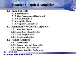
Content • EDFA&Raman hybride amplifier • Security on Physical Level (SPL) technology
Content • EDFA&Raman hybride amplifier • Security on Physical Level (SPL) technology
Seattle Portland Bend Boston Syracuse Rochester Albany Midland Minneapolis Providence Bay City Buffalo Saginaw Flint Boise Grand Rapids Pontiac New Haven Lansing Stamford Madison Detroit Milwaukee Newark NJ Dearborn Kalamazoo Ann Arbor New York Trenton Jackson Chicago Youngstown Cleveland Philadelphia Toledo Pittsburgh South Bend Newark DE Laramie Mountain View Akron Hudson Baltimore Cheyenne Salt Lake City Washington, D.C. Columbus Sacramento Indianapolis Aurora Greenwood Cincinnati Dayton Oakland Hayward Denver Modesto San Francisco St. Louis San Jose Kansas City Santa Clara Richmond Colorado Springs Fresno Pevely Louisville Greensboro Las Vegas Joplin Bakersfield Nashville Raleigh Charlotte Tulsa Palmdale Los Angeles Memphis Oklahoma City Albuquerque Birmingham Atlanta Phoenix San Diego Clanton Lubbock Ft. Worth Jackson Dallas Tucson Abilene Midland Shreveport El Paso Jacksonville Waco Tallahassee Daytona Beach Austin Smithville Baton Rouge Orlando New Orleans Houston San Antonio Tampa McQueeny Legend Systems (Area) Terminal Route Lit Junction Fiber Complete Switch • 19,000+ Miles of Fiber • 500+ Customer Access Locations • 140+ Major Network Access Points Corpus Christi Medley Miami McAllen Harlingen Reynosa Broadwing All-Optical Intelligent Network Intelligent network! Unmanned operation- automaticadjustment!!! Network has been designed as a UNITED system
BroadwingAll-Optical Intelligent Network Amplifier Client port, 2.5 GHz (OC-48), 10 GHz (OC-192) Transmitter Receiver Client port Transmitter Receiver Add-Drop mux • C-band plus optional uninterrupted upgrade to C+L • 2,5 GHz/10 GHz channels, Manchester codingtechnique • EDFA, Raman, andEDFA&Raman hybrid amplifiers • Mesh all-optical all USA network • All nodescommunicatewitheachother – • automaticadjustment!
C + L band loss compensation C - band L - band • In a real fiberthelossesarefiber type specific (SMF, DSF, TW-RS, LEAF, All-Wave) ! • In a real fiberthelossesin L band arefiber span specific !! • In a real fiberlossesarevaryingdepends on environmental conditions– automaticgainadjustmentisrequired!!!
Raman Gainprofile L - band C - band pumps 1400 1500 1530 1565 1570 1605 EDFA firststage EDFA firststage EDFA secondstage EDFA secondstage GFF GFF Raman counter-pump Raman counter-pump Raman co-pump Raman co-pump EDFA & Raman hybrid amplifiers Compromiseis in hybrid EDFA & Raman amplifiers • Raman Amplificationbetter OSNR lowersignal power • lessnonlineareffectslongerpropagationdistance! • Gainspectrumhastobe flat +/- 3 dB in front ofthereceiver!
Raman amplification P – pumps, S – signals i=1…10, k=1…100 1. Raman amplification is described by: • for about 100 channels there are no more than 10 pumps • Least Square Method • Linearization is required. 2. Linearization can be done assuming that mutual pump to pump and signal to signal interactions are negligible: Mki are measured and stored for each span. Is it correct or not ???
Fiber specific approach Mki are measured and stored for each span. Raman Gainprofile L - band C - band pumps 1400 1500 1530 1565 1570 1605 Gk Single pump, linear Gk,0 Pi,0 Pi
Gain Flattening Algorithm – experimental implementation The Least Square Method can be applied straightforward: Gain before adjustment EDFA firststage EDFA secondstage Gain Error GFF Raman counter-pump The pumps minimizing Error Function are applied. The procedure is repeated periodically in order to adjust the deviations.
Gain Flattening Algorithm – nonlinear procedure Raman Gainprofile L - band C - band pumps 1400 1500 1530 1565 1570 1605 Single pump, linear Gk Gk,0 All pumps, nonlinear, working point Pi,0 Pi
Content • EDFA&Raman hybride amplifier • Security on Physical Level (SPL) technology
Encryption • Authentication • Encryption • Authentication LINK Node “Alice” Node “Bob” Information security protection.Security on Physical Level - SPL SPL Eve dropper All-optical communication line can be compromised by tapping signal between nodes. SPL technique protects link against any types of attack.
Manchester coding Quadrature Manchester data spectrum Conventional 10Gb/s dataspectrum • We suggest to use instead of one, for example, 10 GHz channel – two 2x5 GHz sub-channels, which can be generated by the same quadrature modulator used for QPSK modulation. • Physical separation can be done relatively easy with one extra block, fully compatible with the existent infrastructure. • Each sub-channel does not carry any meaningful information, no frames etc. Being separated, each sub-channel can be tapped, but information can not be recovered.
N2 A A N4 N1 B B N3 Link with two extra SPL blocks Demonstration of time delay between subcarriers introduced by SPL-Tx that is compensated back by SPL-Rx for successful signal receiving and interpretation. Red and blue peaks show two sub-channels A and B in spectrum and time domains. “LINK” stands for either the same path, or different paths for two sub-channels. Example of a mesh network with four nodes N1, N2, N3, and N4.
Optional external delay line – security key SPL protection technology: SPL_Tx block A Monitor A, 1% Out A, 99% ISO FBG OS Monitor A+B 50/50 SPL-Tx in OS Out A+B Time delay between sub-channels Out B, 99% OS Monitor B, 1% 99/1 B Optional external delay line – security key SPL-Tx block. Optical signal A+B is subdivided by a circulator and a FBG. Sub-channel A propagates through the upper, while B – through the lower side of SPL-Tx. After that both signals are separated in time using the appropriate delay line in one and/or another arm. For the point to point operation mode, OSs (Optical Switchers) send signals to 99/1 couplers, while for the mesh network operation mode – to 50/50 coupler. For unsecured operation mode (both single 10 GHz channel or 2x5 GHz channels), OS at the input sends signal through the lower path without any modifications.
Compatibility with all existing fiber optic communication network infrastructure. • Classical operational principles which (in contrast with the quantum security technology) make SPL compatible with non-coherent amplification and other all-optical system technologies. • Flexibility in terms of different modulation formats: SPL technology is compatible with non-coherent like NRZ, RZ, and coherent like DP-QPSK etc. modulation formats. Moreover, the same hardware can be designed to provide all necessary modulation formats with SPL and could be dynamically reconfigurable to provide different modulation formats depends on current requirements. • SPL technology does not require major changes in system operation: it requires only one extra block on transmitter and receiver sides, which makes this technology commercially much more attractive in compare with the quantum operation based security. SPL technology: advantages
Conclusion Thanksforyourattention!