Download
1 / 11
110 likes | 248 Views
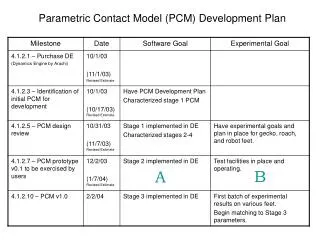
This document outlines the development plan for the Parametric Contact Model (PCM) across multiple stages. Stage 1 introduces a simple contact model with a rigid foot, exploring reaction forces and leg trajectories. Stage 2 builds upon this with time-dependent and random effects, assessing gait strategies. Stage 3 explores more complex geometries, including toes with unique properties, while Stage 4 delves into interactions with varying surfaces and materials. The PCM aims to optimize foot designs for adherence and mobility through simulation and analysis.

E N D
Stage 1 - Simple Contact Ry Model Description: Rigid foot when in contact, free when not Contact is event driven Release is open-loop control based Leg can have linear and rotational spring/damper at the foot Rx Model Complexity: Only 1 PCM parameter – the angle of release Geometry of foot is a simple sphere with appropriate springs/dampers at the ankle Questions Model Can Answer: Measure reaction forces to evaluate leg trajectories and foot compliance, How much does leg squeezing reduce reaction forces? Is 2.5kg excessive? How much do we gain/pay for changing mass? What leg trajectories minimize adhesion forces? How much adhesion will feet need to provide? And for how long?
Stage 2 - Simple Contact with time/random effects Ry < Limit Model Description: Rigid foot when in contact, free when not Contact is state driven with random element Release is time based or load based (including time-dependencies) Rx < Limit Model is extended to handle multiple surfaces Friction Model Complexity: Additional PCM parameters: Slip force thresholds, time dependence, % chance of finding/losing a foothold, sliding friction Geometry of foot is a simple sphere with spring/dampers in leg Questions Model Can Answer: Evaluate gait strategies, foot-hold finding strategies, role of redundancy, Determine if gait is too fast (can’t find a foot-hold) or too slow (begin to slip), Evaluate how to avoid catastrophic failure when a foothold is missed
Stage 3 - Non-trivial Geometry Model Description: Foot with multiple toes (claws & sticky pads) Toes with different contact properties Compliance between toes Claw Pad Model Complexity: Additional PCM parameters: Pad friction model, claw adhesion model Geometry is a set of simple shapes with spring/dampers between Questions Model Can Answer: Foot Design strategies: How many toes? What arraignment? How much compliance between toes? How many claws/pads? We can begin to match experimental data for claws, setae, prototype feet
Stage 4 - Non-trivial Geometry on Surfaces Model Description: Foot with multiple toes (claws & sticky pads) Toes with different contact properties Compliance between toes Details of surface interaction including: Viscoelastic/plastic impact Time dependent friction Statistical surface properties Claw Pad Model Complexity: Additional PCM parameters: Time dependent adhesion or friction, Surface deformation properties, More complex pad and claw models, Velocity dependent impact and friction Geometry is a set of simple shapes with spring/dampers between Questions Model Can Answer: Foot & Behavior designs for finding holds on different surfaces Feed-forward vs. feed-back foothold finding algorithms. We can better match experimental data for claws, setae, prototype feet
Foot/Substrate Contact Pairs Substrates Different Feet Ia A 1 Ib Ic B 3 2 2 1 C B A C 3 Huge number of theoretical Permutations In reality, only a few will be realized
Initial Contact models • Spherical joint created at contact, and persists until deactivated. • Deactivation occurs when one of the following conditions are met: • When the leg angle passes some limit • When the normal or shear force exceeds some limit • After a specific time interval has passed • All of above, plus contact, can have random element 1 ‘Super-foot’ Stages 1&2 Contact models: Ia, Ib, and Ic will be created by varying the parameters of the ‘super-foot’ 2 ‘Claw’ Will be based on experimental data Stage 3 3 ‘Sticky-pad’
A - Simulation Interface Schematic Controller Commands Dynamics Engine (DE) Real-Time Interface (RTI) Code Geometry Creature Description Language (CDL) Text File State Info (2) Contact Initiation, State Information (3) Constraints, Forces (4) Contact information (1) Contact Properties Parametric Contact Model (PCM) Code
class PCMInterface : Public DeContactEvent { /* inherets so that it can be regerestered to handle contacts */ public: PCMInterface(); ~PCMInterface(); ReadConfig(); /* This read a text file to load any parameter changes. It calls PCMContactType->ChangeProperties to implement these changes. */ handle(); /* This function is called when a contact event takes place. It determines the contact material types and decides which contactType to instantiate */ footstatedata update(); /* This function is called each time step (either from the idle function or the RIT, whichever is enforcing the timing. It then calls the appropriate contact's update function */ Member Data: An array of instances of contacts } ------------------------------------------------------------------------------------------------------------------------------------------------------------------------------------------------------------------------------------------------ class PCMContactTypeI { /*this is the actual PCM file for each contact. There is a type for each foot material (I=superfoot, II=claw, III=stickypad, etc.)*/ public: PCMContactTypeI(int substrateType ); /* A different set of parameters is used for each substrate */ ~PCMContactTypeI(); ChangeTypeIProperties(substrateType, name, newValue); { if (name == "cranklimit") cranklimit[substrateType] = newValue } handle(): /* This function creates a spherical constraint at the contact point, so that the foot can rotate, but not translate when it is active --- based on engagepercentage[i]*/ update( substrateType); { /* This function determines whether the spherical constraint is active or not, and returns information to the RTI */ StateData = this->getStateData; for(i=1,i==n,i++) { if (substrateType == i) { if(crankangle > cranklimit[i] * random[i] || normalforce > normallimit[i] * random[i] || shearforce > shearlimit[i] * random[i] || time > t_contact + timelimit[i} * random[i] ) release = True (and call release function)} } return(footStateData) } getStateData(); /*returns information about the current foot state including crankangle, normalforce, shearforce, etc. */ Member Data: cranklimit[numSubstrates] = [ 30 deg, 27 deg, ... ]; , etc. } (1) Read Contact Properties from CDL (2) Get Contact Initiation, Info from DE (3) Create Constrains in DE (2) Get State Initiation, Info from DE (4) Send Contact info to RTI
B - Test Facilities and Sample Materials Claws Various grades of urethane Emily Ma