Download
1 / 18
180 likes | 359 Views
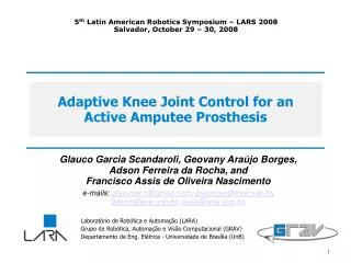
5 th Latin American Robotics Symposium – LARS 2008 Salvador, October 29 – 30, 2008. Adaptive Knee Joint Control for an Active Amputee Prosthesis. Glauco Garcia Scandaroli, Geovany Araújo Borges, Adson Ferreira da Rocha, and Francisco Assis de Oliveira Nascimento

E N D
5th Latin American Robotics Symposium – LARS 2008 Salvador, October 29 – 30, 2008 Adaptive Knee Joint Control for anActive Amputee Prosthesis Glauco Garcia Scandaroli, Geovany Araújo Borges, Adson Ferreira da Rocha, and Francisco Assis de Oliveira Nascimento e-mails: glaucoscn@gmail.com, gaborges@ene.unb.br, adson@ene.unb.br, assis@ene.unb.br. Laboratório de Robótica e Automação (LARA) Grupo de Robótica, Automação e Visão Computacional (GRAV) Departamento de Eng. Elétrica - Universidade de Brasília (UnB) 1
Outline of the presentation • Introduction; • Prosthesis Description; • System Modeling; • Control Strategies; • Conclusions & Ongoing Work. 2
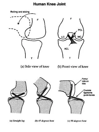
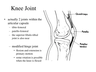
Introduction Rehabilitation robotics: Restoring lost motor functions; Supporting treatment. Importance of knee in locomotion. Active or Passive knee? Three DOF Prosthesis: More similar to human leg.
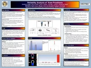
Prosthesis Description • Thee DOF: • Knee (3R15 Otto Bock): • Sagittal Plane. • Foot: • Sagittal Plane; • Frontal Plane. • Actuators: • Servo-Amplifiers + DC Motors. • Movements: • EMG Signals – Knee; • Predictive Model – Foot: • Gyrometers + IR.
System Modeling Simplified Model based on Free Body Diagram. Discrete non-linear model: Variable change: Finally:
System Modeling Parameter Identification: Batch Least Squares. Second order approach: First order approach:
System Modeling Parameter Identification: Batch Least Squares. Second order approach: First order approach:
Control Strategies PID Control: Root-Locus Tuned; Experimentally Tuned. Model Reference Adaptive Control (MRAC). φref . φ ia,k ia controller ν(φk) DAC plant ADC potentiometer
Control Strategies PID – Root Locus Tuned: Kp = 0.0624, Ki = 0.06, Kd = 0.0024, CL Poles: s1 = -4.89, s2 = -0.9917. Rise time: 650 ms.
Control Strategies PID – Root Locus Tuned: Kp = 0.0624, Ki = 0.06, Kd = 0.0024, CL Poles: s1 = -4.89, s2 = -0.9917.
Control Strategies PID – Experimentally Tuned: Kp = 0.1, Ki = 0.111, Kd = 0.0011,
Control Strategies PID – Experimentally Tuned: Kp = 0.1, Ki = 0.111, Kd = 0.0011,
Control Strategies MRAC: Characteristics of reference model: First order; Rise time: 300 ms, Null steady-state error. Parameters: θ1 = 0.099481; θ2 = 0.089133; γ = 1/3.
Control Strategies MRAC: Characteristics of reference model: First order; Rise time: 300 ms, Null steady-state error. Parameters: θ1 = 0.099481; θ2 = 0.089133; γ = 1/3.
Control Strategies MRAC: Characteristics of reference model: First order; Rise time: 300 ms, Null steady-state error. Parameters: θ1 = 0.099481; θ2 = 0.089133; γ = 1/3.
Conclusions & ongoing work System Modeling: First order approximation → No transitory losses. Control Strategies: PID Root-Locus → Steady-state error; PID Experimental → Oscillation, MRAC → Small oscillation. Ongoing work: Control of foot joints; EMG Integration.