Download
1 / 24
340 likes | 719 Views
Silicon Nano Device Laboratory / Dept of ECE. High Performance ALD HfO 2 -Al 2 O 3 Laminate MIM Capacitors for RF and Mixed Signal IC Applications.

E N D
Silicon Nano Device Laboratory / Dept of ECE High Performance ALD HfO2-Al2O3 Laminate MIM Capacitors for RF and Mixed Signal IC Applications Hang Hu1, Shi-Jin Ding1, HF Lim1, Chunxiang Zhu1, M.F. Li1, 2, S.J.Kim1, XF Yu1, JH Chen1, YF Yong1, Byung Jin Cho1, D.S.H. Chan1, Subhash C Rustagi2, MB Yu2, CH Tung2, Anyan Du2, Doan My2, PD Foo2, Albert Chin3, Dim-Lee Kwong4 1SNDL, Dept. of ECE, National Univ. of Singapore, Singapore, 2Institute of Microelectronics, Singapore, 3Dept. of Electronics Eng., National Chiao Tung Univ., Taiwan 4Dept. of Electrical & Computer Eng., Univ. of Texas, Austin, TX 78712, USA
Outline of Presentation • Motivation • Experiment • Results and Discussion • RF characterization • DC properties • Reliability and lifetime • High-κ MIM capacitors comparison • Conclusions
Motivation • Mixed signal MIM capacitor requirement The International Technology Roadmap for Semiconductors, 2002 Edition
Motivation • SiO2 and Si3N4 MIM capacitors usually provide low capacitance density of ~1 fF/μm2. • High-k dielectrics needs to be used for future MIM application according to ITRS roadmap. • HfO2 is a promising high-k material for MIM capacitor. However fast oxygen diffusion. • Al2O3 have the advantage of large band gap, low oxygen diffusivity, however only middle k value.
Experiment • 4 μm SiO2 deposition on Si substrate for isolation • Bottom electrode deposition (Ta/TaN) • Transmission line formation • Dielectric deposition by atomic layer deposition (ALD) • Al2O3 (1nm)/HfO2 (5nm) laminate • Al2O3 as electrode contacting layers • 13, 31, and 43 nm used in our work TEM photo of 13 nm laminate film
Experiment MIM structure Dummy device • Post deposition anneal (420oC) • Contact hole etching • Top metal deposition (TaN/Al) and patterning Final Device structure for characterization
I. RF capacitor model Capacitor modeling in RF regime • Equivalent circuit diagram for MIM capacitor modeling in RF regime
I. S-parameter simulation 13 nm 31 nm 43 nm • Measured and simulated S-parameters for laminate MIM capacitors by IC-CAP using SPICE3 simulator.
I. High frequency response • High frequency response of laminate MIM capacitors from 50 MHz to 20 GHz
I. Cap. versus frequency • The frequency dependence of capacitance density of laminate capacitors (k ~19).
II. J-V characteristics • Typical J-V characteristics of laminate MIM capacitors
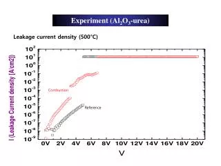
II. J-V characteristics • Leakage obtained at different temperatures for 13 nm MIM capacitor (normalized to JRT: leakage measured at room temperature)
II. Conduction mechanism • Conduction mechanisms of 13 nm laminate MIM capacitor, showing Pool-Frankel conduction at high field.
II. CV characteristics • Quadratic (α) and linear (β) VCCs of laminate MIM capacitors with thicknesses of 13, 31 and 43 nm
II. CV characteristics • Thickness dependence of quadratic VCC (α) for laminate MIM capacitors. The implication is significant for the scaling of the high-k dielectrics.
II. CV characteristics • Frequency dependence of quadratic VCC α for laminate MIM capacitors
II. CV characteristics • Quadratic VCC as a function of stress time. The inset shows time dependence of linear VCC .
II. CV characteristics • Time dependence on VCCs and leakage, under stress condition. The recovery of leakage and VCCs may further prolong lifetime under AC condition.
II. TCC properties • TCC values for laminate MIM capacitors with three different thicknesses
III. Constant voltage stress • Stress time dependence of leakage for a fresh device up to 2000s. The device was re-stressed and re-measured after interrupting stress for 10 hours.
III. Lifetime projection • Life time projection of 13 nm laminate capacitor, using 50% failure time criteria, the extrapolated voltage for 10 years lifetime is 3.3 V.
IV. High-κ MIM cap. comparison • Laminate capacitor is among one of the best for RF capacitor application. [1]. XF Yu et al. EDL. Vol. 24, 2003. [2]. Tsuyoshi. I et al. IEDM 2002, p.940. [3]. C. H. Huang, et al. MTT-S. 2003. [4]. Y. L. Tu. et al VLSI symp. 2003, p.79. [5]. S.J. Kim et al. VLSI symp. 2003, p.77.
Conclusions • High performance HfO2/Al2O3 laminate MIM capacitors have been demonstrated for the first time. • The ALDlaminate MIM capacitors exhibit high C density, superior dielectric stability up to 20 GHz, low leakage current, and promising reliability. • For 13 nm laminate MIM capacitor C density ~12.8 fF/μm2up to 20 GHz ~ 211 ppm/V,Leakage ~ 7.45 nA/cm2at 2 VMeets all requirements for RF bypasscapacitor
Acknowledgment This work was supported by Institute of Microelectronics (Singapore) under Grant R-263-000-233-490 and the National University of Singapore under Grant R-263-000-221-112.