Download
1 / 15
370 likes | 943 Views
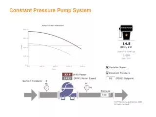
Prev. Pres. Un-Balanced Pressure Compensated, Variable Volume Vane Pump. Pressure Adjusting Screw Set 1,500 PSI. Kidney Shaped Openings Carry Fluid to and From the Cavities Between the Vanes. Symbol. 175 PSI 20 GPM. Case Drain .1 GPM.

E N D
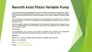
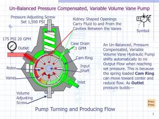
Prev. Pres. Un-Balanced Pressure Compensated, Variable Volume Vane Pump Pressure Adjusting Screw Set 1,500 PSI Kidney Shaped Openings Carry Fluid to and From the Cavities Between the Vanes Symbol 175 PSI 20 GPM Case Drain .1 GPM An Un-Balanced, Pressure Compensated, Variable Volume Vane Hydraulic Pump shifts automatically to no Output Flow when reaching set pressure. This is because the spring loaded Cam Ring can move toward center and reduce flow. As Outlet pressure builds--- Outlet Cam Ring Input Shaft Rotor Vanes Inlet Volume Adjusting Screw Pump Turning and Producing Flow
Prev. Pres. Un-Balanced Pressure Compensated, Variable Volume Vane Pump Pressure Adjusting Screw Set 1,500 PSI Kidney Shaped Openings Carry Fluid to and From the Cavities Between the Vanes Symbol 550 PSI 20 GPM Case Drain .2 GPM Outlet As Outlet pressure builds flow remains nearly constant except for added internal bypass through clearances. When Outlet pressure reaches approximately 80-90% of set pressure-- Cam Ring Input Shaft Rotor Vanes Inlet Volume Adjusting Screw Pump Turning and Producing Flow
Prev. Pres. Un-Balanced Pressure Compensated, Variable Volume Vane Pump Pressure Adjusting Screw Set 1,500 PSI Kidney Shaped Openings Carry Fluid to and From the Cavities Between the Vanes Symbol 1,075 PSI 20 GPM Case Drain .4 GPM Outlet As Outlet pressure builds flow remains nearly constant except for added internal bypass through clearances. When Outlet pressure reaches approximately 80-90% of set pressure-- Cam Ring Input Shaft Rotor Vanes Inlet Volume Adjusting Screw Pump Turning and Producing Flow
Prev. Pres. Un-Balanced Pressure Compensated, Variable Volume Vane Pump Pressure Adjusting Screw Set 1,500 PSI Kidney Shaped Openings Carry Fluid to and From the Cavities Between the Vanes Symbol 1,275 PSI 19 GPM Case Drain .4 GPM As Outlet pressure builds flow remains nearly constant except for added internal bypass through clearances. When Outlet pressure reaches approximately 80-90% of set pressure it forces the Cam Ring to move against the spring. As pressure continues to climb-- Outlet Cam Ring Input Shaft Rotor Vanes Inlet Volume Adjusting Screw Pump Turning and Producing Flow
Prev. Pres. Un-Balanced Pressure Compensated, Variable Volume Vane Pump Pressure Adjusting Screw Set 1,500 PSI Kidney Shaped Openings Carry Fluid to and From the Cavities Between the Vanes Symbol 1,325 PSI 19 GPM Case Drain .5 GPM Outlet As pressure continues to climb the Cam Ring center is forced to move closer to the center of the Rotor and flow reduces more. When the pump reaches pressure setting the Cam Ring--- Cam Ring Input Shaft Rotor Vanes Inlet Volume Adjusting Screw Pump Turning and Producing Flow
Prev. Pres. Un-Balanced Pressure Compensated, Variable Volume Vane Pump Pressure Adjusting Screw Set 1,500 PSI Kidney Shaped Openings Carry Fluid to and From the Cavities Between the Vanes Symbol 1,375 PSI 14 GPM Case Drain .7 GPM Outlet As pressure continues to climb the Cam Ring center is forced to move closer to the center of the Rotor and flow reduces more. When the pump reaches pressure setting the Cam Ring--- Cam Ring Input Shaft Rotor Vanes Inlet Volume Adjusting Screw Pump Turning and Producing Flow
Prev. Pres. Un-Balanced Pressure Compensated, Variable Volume Vane Pump Pressure Adjusting Screw Set 1,500 PSI Kidney Shaped Openings Carry Fluid to and From the Cavities Between the Vanes Symbol 1,425 PSI 9 GPM Case Drain .8 GPM Outlet As pressure continues to climb the Cam Ring center is forced to move closer to the center of the Rotor and flow reduces more. When the pump reaches pressure setting the Cam Ring--- Cam Ring Input Shaft Rotor Vanes Inlet Volume Adjusting Screw Pump Turning and Producing Flow
Prev. Pres. Un-Balanced Pressure Compensated, Variable Volume Vane Pump Pressure Adjusting Screw Set 1,500 PSI Kidney Shaped Openings Carry Fluid to and From the Cavities Between the Vanes Symbol 1,475 PSI 3 GPM Case Drain 1 GPM Outlet As pressure continues to climb the Cam Ring center is forced to move closer to the center of the Rotor and flow reduces more. When the pump reaches pressure setting the Cam Ring--- Cam Ring Input Shaft Rotor Vanes Inlet Volume Adjusting Screw Pump Turning and Producing Flow
Prev. Pres. Un-Balanced Pressure Compensated, Variable Volume Vane Pump Pressure Adjusting Screw Set 1,500 PSI Kidney Shaped Openings Carry Fluid to and From the Cavities Between the Vanes Symbol 1,500 PSI 0 GPM As pressure continues to climb the Cam Ring center is forced to move closer to the center of the Rotor and flow reduces more. When the pump reaches pressure setting the Cam Ring center is near the Rotor center and all Outlet flow stops. Pump volume is still enough to makeup for internal and external bypass. Case Drain 1 GPM Outlet Cam Ring Input Shaft Rotor Vanes Inlet Volume Adjusting Screw Pump Turning, Compensated to No Flow
Prev. Pres. Un-Balanced Pressure Compensated, Variable Volume Vane Pump Pressure Adjusting Screw Set 1,500 PSI Kidney Shaped Openings Carry Fluid to and From the Cavities Between the Vanes Symbol 1,500 PSI 0 GPM As pressure continues to climb the Cam Ring center is forced to move closer to the center of the Rotor and flow reduces more. When the pump reaches pressure setting the Cam Ring center is near the Rotor center and all Outlet flow stops. Pump volume is still enough to makeup for internal and external bypass. Case Drain 1 GPM Outlet Cam Ring Input Shaft Rotor Vanes Inlet Volume Adjusting Screw Pump Turning, Compensated to No Flow
Prev. Pres. Un-Balanced Pressure Compensated, Variable Volume Vane Pump Pressure Adjusting Screw Set 1,500 PSI Kidney Shaped Openings Carry Fluid to and From the Cavities Between the Vanes Symbol 1,500 PSI 0 GPM As pressure continues to climb the Cam Ring center is forced to move closer to the center of the Rotor and flow reduces more. When the pump reaches pressure setting the Cam Ring center is near the Rotor center and all Outlet flow stops. Pump volume is still enough to makeup for internal and external bypass. Case Drain 1 GPM Outlet Cam Ring Input Shaft Rotor Vanes Inlet Volume Adjusting Screw Pump Turning, Compensated to No Flow
Prev. Pres. Un-Balanced Pressure Compensated, Variable Volume Vane Pump Pressure Adjusting Screw Set 1,500 PSI Kidney Shaped Openings Carry Fluid to and From the Cavities Between the Vanes Symbol 1,500 PSI 0 GPM As pressure continues to climb the Cam Ring center is forced to move closer to the center of the Rotor and flow reduces more. When the pump reaches pressure setting the Cam Ring center is near the Rotor center and all Outlet flow stops. Pump volume is still enough to makeup for internal and external bypass. Case Drain 1 GPM Outlet Cam Ring Input Shaft Rotor Vanes Inlet Volume Adjusting Screw Pump Turning, Compensated to No Flow
Prev. Pres. Un-Balanced Pressure Compensated, Variable Volume Vane Pump Pressure Adjusting Screw Set 1,500 PSI Kidney Shaped Openings Carry Fluid to and From the Cavities Between the Vanes Symbol 1,500 PSI 0 GPM As pressure continues to climb the Cam Ring center is forced to move closer to the center of the Rotor and flow reduces more. When the pump reaches pressure setting the Cam Ring center is near the Rotor center and all Outlet flow stops. Pump volume is still enough to makeup for internal and external bypass. Case Drain 1 GPM Outlet Cam Ring Input Shaft Rotor Vanes Inlet Volume Adjusting Screw Pump Turning, Compensated to No Flow
Prev. Pres. Un-Balanced Pressure Compensated, Variable Volume Vane Pump Pressure Adjusting Screw Set 1,500 PSI Kidney Shaped Openings Carry Fluid to and From the Cavities Between the Vanes Symbol 1,500 PSI 0 GPM As pressure continues to climb the Cam Ring center is forced to move closer to the center of the Rotor and flow reduces more. When the pump reaches pressure setting the Cam Ring center is near the Rotor center and all Outlet flow stops. Pump volume is still enough to makeup for internal and external bypass. Case Drain 1 GPM Outlet Cam Ring Input Shaft Rotor Vanes Inlet Volume Adjusting Screw Pump Turning, Compensated to No Flow
Prev. Pres. Un-Balanced Pressure Compensated, Variable Volume Vane Pump Pressure Adjusting Screw Set 1,500 PSI Kidney Shaped Openings Carry Fluid to and From the Cavities Between the Vanes Symbol 1,500 PSI 0 GPM As pressure continues to climb the Cam Ring center is forced to move closer to the center of the Rotor and flow reduces more. When the pump reaches pressure setting the Cam Ring center is near the Rotor center and all Outlet flow stops. Pump volume is still enough to makeup for internal and external bypass. Case Drain 1 GPM Outlet Cam Ring Input Shaft Rotor Vanes Inlet Volume Adjusting Screw Pump Turning, Compensated to No Flow