Download

1 / 19
190 likes | 420 Views
Retrofit Hot Water Heater. Senior Design Team #18 Lacey Ednoff Brianna Beconovich Jarimy Passmore Jesse Poorman. Presentation Overview. Objective Product Specifications Design Concept Component Analysis Theoretical & Experimental Cost Analysis Conclusion

E N D
Retrofit Hot Water Heater Senior Design Team #18 Lacey Ednoff Brianna Beconovich Jarimy Passmore Jesse Poorman
Presentation Overview • Objective • Product Specifications • Design Concept • Component Analysis • Theoretical & Experimental • Cost Analysis • Conclusion • 3D Drawings & Bill of Materials • Future Plans
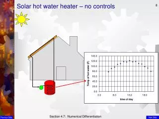
Objective • Use the waste heat from a window AC unit to heat water in a 40 gallon tank • Heat the water initially from 70°F to 120°F in under 3 hours • Utilize customers existing 40 gal hot water heater • Working fluid is R-22 • Assemble for less than $500 • Commercially available parts • Easy installation & reproducible
External Heat Exchanger Coaxial Coil • System utilizes force convection • Requires a pump • May need insulation CPVC piping Douchette Model CX-H075 Pump
Component Analysis Table 1: System components to beanalyzed Blue: Already performed,Red: To be performed prior to final presentation
Selection of AC Window Unit • Assumptions: • Hot water heater is well insulated i.e. no heat loss to surroundings • All of the heat is transferred to the water • ∆T : Temperature change equal to 50 °F • Cp : Specific Heat of Water • mh2o : Mass of water • Total amount of heat transfer required to heat the water: Q = 16,667 BTU • In order to heat the water in 3 hours: • Final selection: Frigidaire ModelQdot = 8000 BTU/hr
Heat Transfer Assumptions • The system is steady state • Closed system i.e. Heat loss from fluid 1 = heat gain by fluid 2 • Thermal properties of the materials are constant • Air properties are constant and evaluated at the appropriate Temperatures • Resistance to heat flow within the copper tubing is negligible, so the temperature is uniform throughout Goal is to determine if the chosen heat exchanger is sized correctly to efficiently transfer the heat from the R-22 fluid to the water
Heat Exchanger Analysis TH in Fluid 1 (warm) TH out TC out Fluid 2 (cold) TC in • Rate of Heat transfer is governed by the overall Heat transfer coefficient, U • Compared the air-cooled system to the modified water-cooled system • Measured Surface Temperatures of the AC unit System • Temp before and after condenser ( TH in & THout) • Temp of ambient air and air after condenser( TC in & TCout) • For the Doucette CX-H075 Coaxial Coil Heat exchanger: • Used manufactures operating Temperatures
Volumetric Flow Rate for Water • Determined Volumetric Flow rate as function of ΔT • Assumed a constant heat transfer rate • Defined ΔT across the heat exchanger in increments of 5 deg
3 1 2 Piping Layout • Divided into 3 sections due to difference in in diameters of pump, heat exchanger, and hot water tank inlets • Section 1: Hot water heater to Heat exchanger • ½” Schedule 40 CPVC • 5 90 deg elbows • 1 Ball valve • 1”- ½” Reduction • Section 2: Heat Exchanger • ½” - 5/8” Expansion • 5/8”- 3/4” Expansion • Section 3: Heat exchanger back to Hot water tank • ¾” Schedule 40 CPVC • 4 90 deg elbows 10
Pressure drop across the piping • Assumptions: For each section of piping Velocity remained constant • Modified Bernoulli Equation • The major and minor losses associated with each section of the piping were calculate individually to find the total pressure drop as a function of change in temperature • Used manufacture specifications for the pressure drop across the heat exchanger This lead to the calculation of the total hydrostatic head which helped in determining an appropriate pump
Hydrostatic Head vs. Volumetric Flow By changing the angle of the ball valve position, the head can be increased
Pump Selection Operating point Required Pressure Head Desired Flow Rate • Pump curve was approximated from manufacture specs • Selection based on cost and low volumetric flow rate Dp/rg 13
Conclusion 1 External Heat Exchanger 2 ¾” CPVC elbow 3 ½” CPVC elbow 4 AC Unit 5 Hot water heater 6 Ball Valve 7 ½” CPVC Pipe 8 ½” Connector 9 ¾” Connector 10 1/2”-5/8”Compression Fitting 11 ¾”-5/8” Compression Fitting
Future Plans • Analysis of the internal heat exchanger design • Overall heat transfer coefficient, Inlet and Outlet Temperature of R-22 • Length of tubing required • Mounting • Pump, A/C Unit • Thermostat • Assembly • Experimental Analysis of working Fluid R-22 • Pressure, Temperature, Mass flow rate • Heat exchanger effectiveness, System efficiency
References • Oak Ridge National Laboratory • http://www.ornl.gov/ • Doucett Industries • http://www.doucettindustries.com • Janna, William. Design of Fluid Thermal Systems 2nd Edition. PWS Publishing Company 1998
Special Thanks!! • Dr. Steve Van Sciver • Dr. Chang Shih • Google