Download
1 / 58
650 likes | 1.02k Views
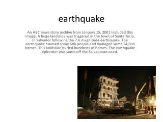
Chapter-09 Masonry Structures under later loads Siddharth shankar Department of Civil(structure) Engineering Pulchowk Campus. F. Earthquake. Engineering representation of earthquake force. Earthquake cause shaking of ground, so a building resting on it will experience motion at its base.

E N D
Chapter-09Masonry Structures under later loads Siddharth shankar Department of Civil(structure) Engineering Pulchowk Campus
F Earthquake Engineering representation of earthquake force • Earthquake cause shaking of ground, so a building resting on it will experience motion at its base. • The roof has a tendency to stay in its original position and the roof experiences a force, called inertia force. • Inertia force is the multiplication of the weight and the acceleration, so larger the weight of the building more the earthquake shaking.
Masonry Structures • Masonry is brittle and tensile and shear strength is very low. • Due to Large mass of masonry structures, heavy weight attracts large amounts of seismic forces. • Wall to wall connection and roof connection is generally weak. • Stress concentration occurs at the corners of windows and doors.
Failure Modes of a Masonry buildings • Out of plane failure • In plane failure • Diaphragm failure • Connection Failure • Failure due to opening of wall • Pounding • Non-structural component failure
Out of Plane Failure • The Earthquake force is perpendicular to the plane. • The wall tends to overturn or bend. • This causes the partial or full collapse of the wall. • This is due to Inadequate anchorage of wall and roof , long and slender wall, etc. • Characterized by vertical cracks at corner, cracks at lintel, roof level and gable wall, etc.
In Plane Failure • The Earthquake force is parallel to the plane • The wall is shear off or bend • X- cracks occurs • Characterized by vertical cracks at wall intersection, separation of corners of two walls, spalling of materials, etc
Diaphragm Failure • Lack of anchoring produce a push of diaphragm against the wall. • Absence of good shear transfer between diaphragms and reaction wall accounts for damage at corner of wall • Rare phenomenon in the event of seismic motion • Separation of wall and diaphragm cause collapse of buildings
Connection failure • For given direction of earthquake, wall A acts as a shear wall and B acts as flexure wall. • If the walls are not tied together wall B overturn (out of olane) and wall A slides (in plane) and collapse occurs. • Masonry units should tied properly
Failure due to opening in walls • Opening will obstruct the flow of forces from one wall to another. • Large opening in shear wall reduces the strength of wall against the inertia forces. • Results diagonal cracks in the areas of masonry between opening and cracks at the level of opening. • Thus, openings should small and away from corners.
Pounding • When the roofs of two adjacent buildings are at different levels, during earthquake, two buildings strike against each other is called pounding. • Pounding results into cracking of the wall.
Non Structural components failure • Falling of plaster from walls and ceiling. • Cracking and overturning of parapets, chimneys, etc. • Cracking and overturning of partition walls. • Cracking of glasses. • Falling of loosely placed objects.
Ductile behaviour of reinforced & unreinforced masonry • It is the capacity of an element or structure to undergo large deformation without failure. • Masonry is brittle in nature. • Ductility of masonry structure is governed by the ductility of masonry units & properties of mortar. • Unreinforced masonry cannot withstand tension so cracks develops. • In-plane & out-of-plane failure is also due to ductility of masonry. • To improve ductility reinforcing bars are embedded in the masonry, called reinforced masonry which can resist the seismic force more than unreinforced masonry.
Brittle Brittle and Ductile force-deformation behavior Force Ductile Δy Δu Deformation
Major causes of failure of masonry buildings • Non-integrity of wall floor and roof. • Configuration – irregularity of building causes torsional effect. • Large opening of the building. • Inappropriate position of opening. • Lack of cross wall in large length of wall. • Lack of reinforcement make the masonry building brittle. • Pounding effect. • Lack of anchoring element between two walls.
Horizontal bands for integrity Connecting peripheral walls for structural robustness and integrity • Plinth band • Lintel band • Roof band • Gable band
Roof structure • Light and strong roof is desirable. • Secure tiles/slates or use GI sheets. • Good jointing in trusses Concrete floors in 1:2:4 concrete with reinforcement in both directions and bend up near supports.
Chapter-10Testing of masonry elementssiddharth shankarPulchowk Campus Department of Civil Engineering
Normally carried out:1. Periodically to evaluate the performance of building • 2.To gather information on old building in order to ascertain the methods of repair or to demolish • 3. To ascertain the strength of concrete if cube tests failed.
NON DESTRUCTIVE TEST (NDT) • Elastic wave tomography • Rebound Hammer / Schmidt Hammer • Ultrasonic Pulse Velocity • Impact Echo Test • X-Rays • Flat Jack Test
Elastic wave tomography • Technique used for locating shallow delaminations, cracks, and voids. • Elastic wave tomography is based on two basic principles from heat transfer: conduction and radiation. Sound materials with no voids, gaps, or cracks are more thermally conductive than materials that are delaminated or contain moisture. • This allows rapid areal mapping of internal conditions. It should be noted that the IT method is most useful for the detection of shallow defects and flaws. • Tests For: Voids, Cracks, Moisture.
Rebound Method • Can be used to determine the in-place compressive strength of concrete within a range of 1500 – 8000 psi (10-55MPa) • A quick and simple mean of checking concrete uniformity. • Measure the distance of rebound of a spring-loaded plunger after it struck a smooth concrete surface. • Results of the test can be affected by factors such as smoothness of concrete surface, size, shape, rigidity of specimen, age & moisture condition. • Type of coarse aggregate & the carbonation of the surface.
Nondestructive Test Methods • Rebound Hammer Tests • Schmidt Hammer
Ultrasonic Pulse Velocity • It uses measurement of the speed of ultrasonic pulses through the concrete to correlate concrete strength to standard strength. • Allows the determination of compressive concrete strength and location of cracks. • It will identify non homogenous condition in the structure such as honeycomb, voids and cracks. • Size of cracks can also be determined.