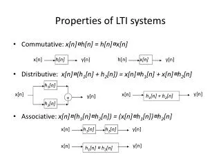
LTI System Analysis
LTI System Analysis. Zero-State LTIC System Response. LTIC: Linear Time-Invariant Continuous-time System response = zero-input response + zero-state response Approaches to find the zero-state response Time-domain solutions to the differential equation

LTI System Analysis
E N D
Presentation Transcript
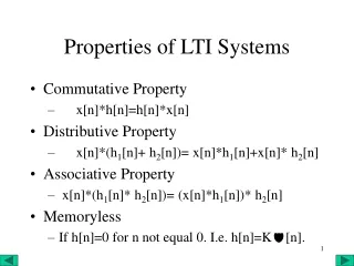
Zero-State LTIC System Response • LTIC: Linear Time-Invariant Continuous-time • System response =zero-input response + zero-state response • Approaches to find the zero-state response Time-domain solutions to the differential equation Convolution in time domain: y(t) = f(t) * h(t) Continuous-time Fourier transform: Y(w) = F(w) H(w) Laplace transform: Y(s) = F(s) H(s)
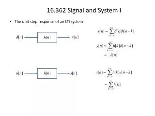
Example #1 • Transfer function1/(s+2) and input e -t u(t) • Either way takes about the same amount of work
Example #2: Laplace is Easier • Transfer function1/(s+2) and input u(t)
Example #3: Laplace Cannot Work • Transfer function1/(s+2) and input et u(-t)
Signal Distortion • Total distortion Y(w) = F(w) H(w) H(w) is the frequency response • Magnitude distortion |Y(w)| = |F(w)| |H(w)| • Phase distortion Y(w) = (F(w) H(w)) = F(w) + H(w) • All-pass filter: magnitude response of 1 Example: Phase shifting by 90° to convert cos(2pfct) into sin(2pfct) known as a Hilbert transformer
Distortionless Transmission • Want distortionless transmission: input and output signals have identical shapes, differ by a multiplicative constant, and may be delayed y(t) = k f(t - t) Y(w) = k e - j w t F(w) H(w) = Y(w)/F(w) = k e - j w t Magnitude response: |H(w)| = k Phase response (linear): H(w) = – w t Time delay is the negative of the derivative of H(w) w/r to w • Channels have distortion Receiver needs to know the channel distortion Receiver uses an equalizer.
Speech signals Use phase differences to locate a speaker Once locked onto a speaker, our ears are relatively insensitive to phase distortion in speech from that speaker (underlies speech compression systems, e.g. digital cell phones.) Linear phase crucial Audio Images Communication systems Linear phase response Need FIR filters Realizable IIR filters cannot achieve linear phase response Importance of Linear phase