When materials are getting tired…
When materials are getting tired… . Sub-topics Cyclic stresses Fatigue Crack propagation Resistance to fatigue. Fatigue: facts.

When materials are getting tired…
E N D
Presentation Transcript
When materials are getting tired… Sub-topics Cyclic stresses Fatigue Crack propagation Resistance to fatigue
Fatigue: facts • Fatigue is important as it is the largest cause of failure in metals, estimated to comprise approximately 90% of all metallic failures; polymers and ceramics are also susceptible to this type of failure.
Fatigue failure Fatigue failures occur due to cyclic loading at stresses below a material’s yield strength https://www.youtube.com/watch?v=dGQfUWvP0II
Schematic of the stress cycling on the underside of a wing Loading cycles can be in the millions for an aircraft; fatigue testing must employ millions of fatigue cycles to provide meaningful design data. https://www.youtube.com/watch?v=ywDsB3umK2Y
Fatigue • Fatigue is a form of failure that occurs in structures subjected to dynamic and fluctuating stresses • Under these circumstances it is possible for failure to occur at a stress level considerably lower than the tensile or yield strength for a static load. • It is catastrophic and insidious, occurring very suddenly and without warning. • Primary design criterion in rotating parts. • Fatigue as a name for the phenomenon based on the notion of a material becoming “tired”, i.e. failing at less than its nominal strength. • Cyclic strain (stress) leads to fatigue failure. • Occurs in metals and polymers but rarely in ceramics. • Alsoan issue for “static” parts, e.g. bridges.
Fatigue: general characteristics • Most applications of structural materials involve cyclic loadinge. • Fatigue failure surfaces have three characteristic features: • A (near-)surface defect as the origin of the crack • Striations corresponding to slow, intermittent crack growth • Dull, fibrous brittle fracture surface (rapid growth). • Life of structural components generally limited by cyclic loading, not static strength. • Most environmental factors shorten life. the crack length exceeds a critical value at the applied stress.
Three stages of fatigue • First, a tiny crack initiates or nucleates often at a time well after loading begins. Normally, nucleation sites are located at or near the surface, where the stress is at a maximum, and include surface defects such as scratches or pits, sharp corners due to poor design or manufacture, inclusions, grain boundaries, or dislocation concentrations. • Next, the crack gradually propagates as the load continues to cycle. • Finally, a sudden fracture of the material occurs when the remaining cross-section of the material is too small to support the applied load. Thus, components fail by fatigue because even though the overall applied stress may remain below the yield stress, at a local length scale, the stress intensity exceeds the tensile strength. • For fatigue to occur, at least part of the stress in the material has to be tensile.
Factors causing fatigue failure 1) A maximum tensile stress of sufficiently high value. 2) A large amount of variation or fluctuation in the applied stress. 3) A sufficiently large number of cycles of the applied stress. • Stress concentration • Corrosion • Temperature • Overload • Metallurgical structure • Residual stress • Combined stress
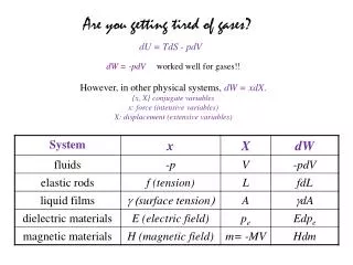
Random stress cycle. Cyclic stresses Reversed stress cycle, in which the stress alternates from a maximum tensile stress to a maximum compressive stress of equal magnitude Repeated stress cycle, in which maximum and minimum stresses are asymmetrical relative to the zero stress level; mean stress m, range of stress r , and stress amplitude a are indicated.
Parameters mean stress range of stress stress amplitude stress ratio R
S-N Curves • S-N [stress-number of cycles to failure] curve defines number of cycles-to-failure for given cyclic stress. • Rotating-beam fatigue test is standard; also alternating tension-compression. • Plot stress versus the log(number of cycles to failure), log(Nf). • For frequencies < 200Hz, metals are insensitive to frequency; fatigue life in polymers isfrequency dependent. rotating-bending tests
S–N behavior Stress amplitude (S) versus logarithm of the number of cycles to fatigue failure (N) for a material that displays a fatigue limit The higher the magnitude of the stress, the smaller the number of cycles the material is capable to sustain before failure There is a limiting stress level, called the fatigue limit (also sometimes theendurance limit), belowwhich fatigue failure will not occur.
Endurance Limits • Some materials exhibit endurance limits, i.e. a stress below which the life is infinite: • Steels typically show an endurance limit of about 40% - 60% of yield strength; this is typically associated with the presence of a solutes (carbon, nitrogen) that pines dislocations and prevents dislocation motion at small displacements or strains. • Aluminum alloys do not show endurance limits; this is related to the absence of dislocation-pinning solutes. • At large Nf, the lifetime is dominated by nucleation. • Therefore strengthening the surface (shot penning) is beneficial to delay crack nucleation and extend life.
S–N behavior Stress amplitude (S) versus logarithm of the number of cycles to fatigue failure (N) for a material that does not display a fatigue limit. Fatigue will ultimately occur regardless of the magnitude of the stress. For these materials, the fatigue response is specified as fatigue strength, which is defined as the stress level at which failure will occur for some specified number of cycles (e.g., 107 cycles). Most nonferrous alloys (e.g., aluminum, copper, magnesium) do not have a fatigue limit, in that the S–N curve continues its downward trend at increasingly greater N values
Fatigue life fatigue life Nfcharacterizes a material’s fatigue behavior It is the number of cycles to cause failure at a specified stress level, as taken from the S–N plot There always exists considerable scatter in fatigue data, that is, a variation in the measured N value for a number of specimens tested at the same stress level. This may lead to significant design uncertainties when fatigue life and/or fatigue limit (or strength) are being considered. The scatter in results is a consequence of the fatigue sensitivity to a number of test and material parameters that are impossible to control precisely. These parameters include specimen fabrication and surface preparation, metallurgical variables, specimen alignment in the apparatus, mean stress, and test frequency.
Statistical nature of fatigue • Because the S-N fatigue data is normally scattered, it should be therefore represented on aprobability basis. • Considerable number ofspecimens is used to obtain statistical parameters. • At σ1, 1% of specimens would be expected to fail at N1 cycles. • 50% of specimens would be expected to fail at N2 cycles. • For engineering purposes, it is sufficiently accurate to assume a logarithmic normal distribution of fatigue life in the region of the probability of failure of P = 0.10 to P = 0.90.
Fatigue S–N probability of failure curves for a 7075-T6 aluminum alloy The data obtained is normally scattered at the same stress level by using several specimens. This requires statistic approachto define the fatigue limit. The probability of failure Constant probability curves
High- cyclic fatigue • For low stress levels wherein deformations are totally elastic, longer lives result. This is called high-cycle fatigue inasmuch as relatively large numbers of cycles are required to produce fatigue failure. • High-cycle fatigue is associated with fatigue lives greater than about 104 to 107cycles. The S-N curve in the high-cycle region is sometimes described by the Basquin equation p and C are empirical constants
Low- cycle fatigue • is associated with relatively high loads that produce not only elastic strain but also some plastic strain during each cycle. • Consequently, fatigue lives are relatively short occurs at less than about 104 to 105 cycles
Design of a rotating shaft • A solid shaft for a cement oven produced from tool steel must be 240 cm long and must survive continuous operation for one year with an applied load of 55,600 N. • The shaft makes one revolution per minute during operation. • Design a shaft that will satisfy these requirements. The maximum stress acting on this type of specimen
Process of fatigue failure Characterized by three distinct steps: • (1) crack initiation, wherein a small crack forms at some point of high stress concentration; • (2) crack propagation, during which this crack advances incrementally with each stress cycle; • (3) final failure, which occurs very rapidly once the advancing crack has reached a critical size. The fatigue life Nf , the total number of cycles to failure, therefore can be taken as the sum of the number of cycles for crack initiation Ni and crack propagation Np The contribution of the final failure step to the total fatigue life is insignificant since it occurs so rapidly
Crack initiation • Cracks associated with fatigue failure almost always initiate (or nucleate) on the surface of a component at some point of stress concentration. • Crack nucleation sites include surface scratches, sharp fillets, keyways, threads, dents, and the like. • In addition, cyclic loading can produce microscopic surface discontinuities resulting from dislocation slip steps which may also act as stress raisers, and therefore as crack initiation sites.
Initiation of fatigue crack and slipband crack growth (stage I) • Fatigue cracks are normally initiated at a free surface. Slip lines are formed during the first few thousand cycles of stress. • Back and forth fine slip movements of fatigue could build up notches or ridges at the surface => act as stress raiser => initiate crack • In stage I, the fatigue crack tends to propagate initially along slip planes (extrusion and intrusion of persistent slip bands) and later take the direction normal to the maximum tensile stress (stage II). • The crack propagation rate in stage I is generally very low on the order of nm/cycles giving featurelesssurface.
Crack propagation • Once a stable crack has nucleated, it then initially propagates very slowly and, in polycrystalline metals, along crystallographic planes of high shear stress; this is stage I propagation • This stage may constitute a large or small fraction of the total fatigue life depending on stress level and the nature of the test specimen; high stresses and the presence of notches favor a short lived stage I. • In polycrystalline metals, cracks normally extend through only several grains during this propagation stage. • The fatigue surface that is formed during stage I propagation has a flat and featureless appearance
Fatigue crack propagationmechanism repetitive crack tip plastic blunting and sharpening zero or maximum compressive load small compressive load small tensile load zero or maximum compressive load maximum tensile load small tensile load
Fatigue crack propagatiion For design against fatigue failure, fracturemechanics is utilised to monitor the fatigue crack growth rate in the stage II The fatigue crack growth rate da/dNvaries with stress intensity factor range K, which is a function of stress range σ and crack length a.
Stage II • ΔK is the stress intensity factor range at the crack tip Schematic representation of logarithm fatigue crack propagation rate da/dNversus logarithm stress intensity factor range K.
Crack propagation rate • Life of a structural component may be related to the rate of crack growth. • During stage II propagation, cracks may grow from a barely perceivable size to some critical length. Crack length versus the number of cycles at stress levels 1 and 2. Crack growth rate da/dNis indicated at crack length a1 for both stress levels. The parameters A and m are constants for the particular material
Crack growth rate and number of cycles • Knowledge of crack growth rate is of assistance in designing components and in nondestructive evaluation to determine if a crack poses imminent danger to the structure. Integration between the initial size of a crack and the crack size required for fracture to occur ai is the initial flaw size and ac is the flaw size required for fracture.
Design of a fatigue resistant plate • A high-strength steel plate, which has a plane strain fracture toughness of 80 Mpa m1/2 is alternately loaded in tension to 500 MPa and in compression to 60 MPa. • The plate is to survive for 10 years with the stress being applied at a frequency of once every 5 minutes. • Design a manufacturing and testing procedure that ensures that the component will serve as intended. • Assume a geometry factor Y = 1.0.
Forensic fracture case • K1c of the tank material measured to be 45 MPa√m • 10 mm crack found in longitudinal weld Stress based on maximum design pressure Stress at which a plate with the given K1cwill fail with a 10 mm crack
How long is a life? • How long would it have lasted before fatigue grew the crack to an unstable size? Residual life = 7 x 10⁶ cycles
Design for fatigue 100 resolutions per second High-cycle fatigue – 3 x 10⁶ cycles At least 300 resolutions per second
Selection chart for con-rod based on material index Further selection criteria includes the use of S-N curves For a design life of 2.5 x 10⁶ cycles, a stress of 620 MPa can be safely applied
Features of fatigue failure • two types of markings termed beachmarks and striations • indicate the position of the crack tip at some point in time and appear as concentric ridges that expand away from the crack initiation site(s), frequently in a circular or semicircular pattern. Fracture surface of a rotating steel shaft that experienced fatigue failure. Beachmark ridges are visible in the photograph
FACTORS THAT AFFECT FATIGUE LIFE • Stress concentration • • Size effect • • Surface effects • • Combined stresses • • Cumulative fatigue damage andsequence effects • • Metallurgical variables • • Corrosion • • Temperature Demonstration of influence of mean stress m on S–N fatigue behavior
Effect of mean stress, stress range and stress intensity (notch) on S-N fatigue curve
Effect of stress concentration on fatigue Kt is theoretical stress-concentration factor, depending on elasticity of crack tip Kf is fatigue notch factor, ratio of fatigue strength of notched and unnotched specimens
Problem What design is better? Demonstration of how design can reduce stress mplification. Poor design: sharp corner. Good design: fatigue lifetime improved by incorporating rounded fillet into a rotating shaft at the point where there is a change in diameter.
Surface effects on fatiigue • Fatigue properties are very sensitive to surface conditions, • Fatigue initiation normally starts at the surface since the maximum stress is at the surface. • The factors which affect the surface of a fatigue specimen can be roughly divided into three categories
Surface roughness • Different surface finishes produced by different machining processes can appreciably affect fatigue performance. • Polished surface (very fine scratches), normally known as ‘par bar’ which is used in laboratory, gives the best fatigue strength
Surface residual stress Superposition of applied and residual stresses Compressive forces on the surface resist crack growth – method of producing these stresses is Shot penning Shows the elastic stress distribution in a beam with no residual stress. Typical residual stress distribution produced by shot peening where the high compressive stress is balanced by the tensile stress underneath. The stress distribution due to the algebraic summation of the external bending stress and the residual stress
Commercial methods introducingfavourable compressive stress • Surface rolling- Compressive stress is introduced in between the rollers during sheet rolling • Shot peening- Projecting fine steel or cast-iron shot against the surface at high velocity • Polishing - Reducing surface scratches • Thermal stress- Quenching or surface treatments introduce volume change giving compressive stress.
Cumulative fatiigue damage andsequence effects on fatiigue • Practically, levels of stress are not held constant as in S-N tests, but can vary below or above the designed stress level • Overstressing : The initial applied stress level is higher than the fatigue limit for a short period of time beyond failure, then cyclic stressing below the fatigue limit. This overstressing reduces the fatigue limit. • • Understressing : The initial applied stress level is lower than the fatigue limit for a period of time, then cyclic stressing above the fatigue limit. This understressing increases the fatigue limit (might be due to strain hardening on the surface.
Effects of metallurgical variablleson fatigue • • Fatigue property is normally greatly improved by changing the designs or, reducing stress concentration, introducing compressive stress on the surface. • • Few attempts have paid on improving metallurgical structure to improve fatigue properties but it is still important. • • Fatigue property is frequently correlated with tensile properties.
Fatigue strength improvement bycontrolling metallurgical variables Grain size has its greatest effect on fatigue life in the low-stress, high cycle regime
Fatigue strength improvement bycontrolling metallurgical variables • • Promote homogeneous slip /plastic deformation through thermo-mechanical processing => reduces residual stress/ stress concentration. • • Heat treatments to give hardened surface but should avoid stress concentration. • • Avoid inclusions = >stress concentration => fatigue strength • • Interstitial atoms increase yield strength , if plus strain aging => fatigue strength
Effect of corrosion on fatigue • Fatigue corrosion occurs when material is subjected to cyclic stress in a corrosive condition. • Corrosive attack produces pittingon metal surface. Pits act as notches => fatigue strength • Chemical attack greatly acceleratesthe rate of fatigue crack propagation Role of a corrosive environment on fatigue crack propagation Corrosion fatigue of brass
Thermal effect • induced at elevated temperatures by fluctuating thermal stresses; • mechanical stresses from an external source need not be present • The origin of these thermal stresses is the restraint to the dimensional expansion and/or contraction that would normally occur in a structural member with variations in temperature