Understanding MPLS: Label Substitution, Routing Techniques, and Protocols Overview
This tutorial provides a comprehensive overview of Multi-Protocol Label Switching (MPLS) and its associated concepts, including label encapsulations and distribution protocols. It explains various routing techniques such as hop-by-hop routing, source routing, and broadcast methods to reach a destination. The tutorial also discusses the importance of labels in protocols like ATM and Frame Relay, detailing how MPLS enhances traffic engineering and QoS. Key aspects such as the Label Distribution Protocol (LDP) and forwarding equivalence classes are covered, making it an essential resource for networking professionals.

Understanding MPLS: Label Substitution, Routing Techniques, and Protocols Overview
E N D
Presentation Transcript
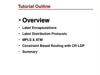
Tutorial Outline • Overview • Label Encapsulations • Label Distribution Protocols • MPLS & ATM • Constraint Based Routing with CR-LDP • Summary
“Label Substitution” what is it? One of the many ways of getting from A to B: • BROADCAST: Go everywhere, stop when you get to B, never ask for directions. • HOP BY HOP ROUTING: Continually ask who’s closer to B go there, repeat … stop when you get to B. “Going to B? You’d better go to X, its on the way”. • SOURCE ROUTING: Ask for a list (that you carry with you) of places to go that eventually lead you to B. “Going to B? Go straight 5 blocks, take the next left, 6 more blocks and take a right at the lights”.
Label Substitution LANE#1 TURN RIGHT USE LANE#2 • Have a friend go to B ahead of you using one of the previous two techniques. At every road they reserve a lane just for you. At ever intersection they post a big sign that says for a given lane which way to turn and what new lane to take. LANE#1 LANE#2
A label by any other name ... There are many examples of label substitution protocols already in existence. • ATM - label is called VPI/VCI and travels with cell. • Frame Relay - label is called a DLCI and travels with frame. • TDM - label is called a timeslot its implied, like a lane. • X25 - a label is an LCN • Proprietary PORS, TAG etc.. • One day perhaps Frequency substitution where label is a light frequency?
SO WHAT IS MPLS ? • Hop-by-hop or source routing to establish labels • Uses label native to the media • Multi level label substitution transport
ROUTE AT EDGE, SWITCH IN CORE IP #L1 IP #L2 IP #L3 IP IP IP Forwarding IP Forwarding LABEL SWITCHING
MPLS: HOW DOES IT WORK UDP-Hello UDP-Hello TCP-open Initialization(s) Label request IP #L2 Label mapping TIME TIME
WHY MPLS ? • Leverage existing ATM hardware • Ultra fast forwarding • IP Traffic Engineering • Constraint-based Routing • Virtual Private Networks • Controllable tunneling mechanism • Voice/Video on IP • Delay variation + QoS constraints
BEST OF BOTH WORLDS IP MPLS+IP ATM CIRCUITSWITCHING PACKETROUTING HYBRID • MPLS + IP form a middle ground that combines the best of IP and the best of circuit switching technologies. • ATM and Frame Relay cannot easily come to the middle so IP has!!
MPLS Terminology • LDP: Label Distribution Protocol • LSP: Label Switched Path • FEC: Forwarding Equivalence Class • LSR: Label Switching Router • LER: Label Edge Router (Useful term not in standards)
Forwarding Equivalence Classes IP1 IP1 IP1 IP2 IP1 IP2 IP2 IP1 #L1 #L3 #L1 #L2 #L2 #L3 IP2 IP2 LSR LSR LER LER LSP Packets are destined for different address prefixes, but can be mapped to common path • FEC = “A subset of packets that are all treated the same way by a router” • The concept of FECs provides for a great deal of flexibility and scalability • In conventional routing, a packet is assigned to a FEC at each hop (i.e. L3 look-up), in MPLS it is only done once at the network ingress
MPLS BUILT ON STANDARD IP 3 47.1 1 2 1 3 2 1 47.2 3 47.3 2 • Destination based forwarding tables as built by OSPF, IS-IS, RIP, etc.
IP FORWARDING USED BY HOP-BY-HOP CONTROL IP 47.1.1.1 47.1 1 IP 47.1.1.1 2 IP 47.1.1.1 1 3 2 IP 47.1.1.1 1 47.2 3 47.3 2
MPLS Label Distribution Request: 47.1 Request: 47.1 Mapping: 0.50 Mapping: 0.40 1 47.1 3 3 2 1 1 2 47.3 3 47.2 2
Label Switched Path (LSP) IP 47.1.1.1 IP 47.1.1.1 1 47.1 3 3 2 1 1 2 47.3 3 47.2 2
EXPLICITLY ROUTED LSP ER-LSP IP 47.1.1.1 IP 47.1.1.1 1 47.1 3 3 2 1 1 2 47.3 3 47.2 2
Tutorial Outline • Overview • Label Encapsulations • Label Distribution Protocols • MPLS & ATM • Constraint Based Routing with CR-LDP • Summary
Label Encapsulation ATM FR Ethernet PPP L2 VPI VCI DLCI “Shim Label” Label “Shim Label” ……. IP | PAYLOAD MPLS Encapsulation is specified over various media types. Top labels may use existing format, lower label(s) use a new “shim” label format.
MPLS Link Layers • MPLS is intended to run over multiple link layers • Specifications for the following link layers currently exist: • ATM: label contained in VCI/VPI field of ATM header • Frame Relay: label contained in DLCI field in FR header • PPP/LAN: uses ‘shim’ header inserted between L2 and L3 headers • Translation between link layers types must be supported MPLS intended to be “multi-protocol” below as well as above
MPLS Encapsulation - ATM ATM LSR constrained by the cell format imposed by existing ATM standards 5 Octets ATM Header Format VPI VCI PT HEC CLP Label Option 1 Label Combined Label Option 2 Option 3 ATM VPI (Tunnel) Label AAL 5 PDU Frame (nx48 bytes) ••• n 1 Network Layer Header and Packet (eg. IP) Generic Label Encap. (PPP/LAN format) AAL5 Trailer ATM SAR 48 Bytes 48 Bytes ATM Header • • • ATM Payload • Top 1 or 2 labels are contained in the VPI/VCI fields of ATM header • - one in each or single label in combined field, negotiated by LDP • Further fields in stack are encoded with ‘shim’ header in PPP/LAN format • - must be at least one, with bottom label distinguished with ‘explicit NULL’ • TTL is carried in top label in stack, as a proxy for ATM header (that lacks TTL)
MPLS Encapsulation - Frame Relay Generic Encap. (PPP/LAN Format) Q.922 Header Layer 3 Header and Packet ••• n 1 C/ R FE CN E A BE CN D E E A DLCI Size = 10, 17, 23 Bits DLCI DLCI • Current label value carried in DLCI field of Frame Relay header • Can use either 2 or 4 octet Q.922 Address (10, 17, 23 bytes) • Generic encapsulation contains n labels for stack of depth n • - top label contains TTL (which FR header lacks), ‘explicit NULL’ label value
MPLS Encapsulation - PPP & LAN Data Links MPLS ‘Shim’ Headers (1-n) ••• n 1 Network Layer Header and Packet (eg. IP) Layer 2 Header (eg. PPP, 802.3) 4 Octets Label Stack Entry Format TTL Label Exp. S Label: Label Value, 20 bits (0-16 reserved) Exp.: Experimental, 3 bits (was Class of Service) S: Bottom of Stack, 1 bit (1 = last entry in label stack) TTL: Time to Live, 8 bits • Network layer must be inferable from value of bottom label of the stack • TTL must be set to the value of the IP TTL field when packet is first labelled • When last label is popped off stack, MPLS TTL to be copied to IP TTL field • Pushing multiple labels may cause length of frame to exceed layer-2 MTU • - LSR must support “Max. IP Datagram Size for Labelling” parameter • - any unlabelled datagram greater in size than this parameter is to be fragmented MPLS on PPP links and LANs uses ‘Shim’ Header Inserted Between Layer 2 and Layer 3 Headers
Tutorial Outline • Overview • Label Encapsulations • Label Distribution Protocols • MPLS & ATM • IETF Status • Nortel’s Activity • Summary
Label Distribution Protocols • Overview of Hop-by-hop & Explicit • Label Distribution Protocol (LDP) • Constraint-based Routing LDP (CR-LDP) • Extensions to RSVP • Extensions to BGP
Comparison - Hop-by-Hop vs. Explicit Routing Hop-by-Hop Routing Explicit Routing • Distributes routing of control traffic • Builds a set of trees either fragment by fragment like a random fill, or backwards, or forwards in organized manner. • Reroute on failure impacted by convergence time of routing protocol • Existing routing protocols are destination prefix based • Difficult to perform traffic engineering, QoS-based routing • Source routing of control traffic • Builds a path from source to dest • Requires manual provisioning, or automated creation mechanisms. • LSPs can be ranked so some reroute very quickly and/or backup paths may be pre-provisioned for rapid restoration • Operator has routing flexibility (policy-based, QoS-based, • Adapts well to traffic engineering Explicit routing shows great promise for traffic engineering
Explicit Routing - MPLS vs. Traditional Routing • Connectionless nature of IP implies that routing is based on information in each packet header • Source routing is possible, but path must be contained in each IP header • Lengthy paths increase size of IP header, make it variable size, increase overhead • Some gigabit routers require ‘slow path’ option-based routing of IP packets • Source routing has not been widely adopted in IP and is seen as impractical • Some network operators may filter source routed packets for security reasons • MPLS’s enables the use of source routing by its connection-oriented capabilities • - paths can be explicitly set up through the network • - the ‘label’ can now represent the explicitly routed path • Loose and strict source routing can be supported MPLS makes the use of source routing in the Internet practical
Label Distribution Protocols • Overview of Hop-by-hop & Explicit • Label Distribution Protocol (LDP) • Constraint-based Routing LDP (CR-LDP) • Extensions to RSVP • Extensions to BGP
Label Distribution Protocol (LDP) - Purpose Label distribution ensures that adjacent routers have a common view of FEC <-> label bindings Routing Table: Addr-prefix Next Hop 47.0.0.0/8 LSR3 Routing Table: Addr-prefix Next Hop 47.0.0.0/8 LSR2 LSR1 LSR3 LSR2 IP Packet 47.80.55.3 Label Information Base: Label-In FEC Label-Out XX 47.0.0.0/8 17 For 47.0.0.0/8 use label ‘17’ Label Information Base: Label-In FEC Label-Out 17 47.0.0.0/8 XX Step 2: LSR communicates binding to adjacent LSR Step 3: LSR inserts label value into forwarding base Step 1: LSR creates binding between FEC and label value Common understanding of which FEC the label is referring to! Label distribution can either piggyback on top of an existing routing protocol, or a dedicated label distribution protocol (LDP) can be created
Label Distribution - Methods Label Distribution can take place using one of two possible methods Downstream Label Distribution Downstream-on-Demand Label Distribution LSR2 LSR1 LSR2 LSR1 Label-FEC Binding Request for Binding • LSR2 and LSR1 are said to have an “LDP adjacency” (LSR2 being the downstream LSR) • LSR2 discovers a ‘next hop’ for a particular FEC • LSR2 generates a label for the FEC and communicates the binding to LSR1 • LSR1 inserts the binding into its forwarding tables • If LSR2 is the next hop for the FEC, LSR1 can use that label knowing that its meaning is understood Label-FEC Binding • LSR1 recognizes LSR2 as its next-hop for an FEC • A request is made to LSR2 for a binding between the FEC and a label • If LSR2 recognizes the FEC and has a next hop for it, it creates a binding and replies to LSR1 • Both LSRs then have a common understanding Both methods are supported, even in the same network at the same time For any single adjacency, LDP negotiation must agree on a common method
DOWNSTREAM ON DEMAND MAKING SPF TREE COPY IN H/W #14 #311 #216 #99 #311 #963 #311 D D? D? #963 #14 D? D? #612 D D? #462 D D? D D #311 #99 #5 D D D D? D?
Label Distribution Protocols • Overview of Hop-by-hop & Explicit • Label Distribution Protocol (LDP) • Constraint-based Routing LDP (CR-LDP) • Extensions to RSVP
Constraint-based LSP Setup using LDP • Uses LDP Messages (request, map, notify) • Shares TCP/IP connection with LDP • Can coexist with vanilla LDP and inter-work with it, or can exist as an entity on its own • Introduces additional data to the vanilla LDP messages to signal ER, and other “Constraints”
ER-LSP Setup using CR-LDP 2. Request message processed and next node determined. Path list modified to <C,D> 3. Request message terminates. 1. Label Request message. It contains ER path < B,C,D> 6. When LER A receives label mapping, the ER established. 5. LSR C receives label to use for sending data to LER D. Label table updated 4. Label mapping message originates. LER A LSR B LSR C LER D ER Label Switched Path Ingress Egress
CR-LDP PREEMPTION A CR-LSP carries an LSP priority. This priority can be used to allow new LSPs to bump existing LSPs of lower priority in order to steal their resources. This is especially useful during times of failure and allows you to rank the LSPs such that the most important obtain resources before less important LSPs. These are called the setupPriority and a holdingPriority and 8 levels are provided.
CR-LDP PREEMPTION When an LSP is established its setupPriority is compared with the holdingPriority of existing LSPs, any with lower holdingPriority may be bumped to obtain their resources. This process may continue in a domino fashion until the lowest holdingPriority LSPs either clear or are on the worst routes.
ER-LSP setup using RSVP 3. Resv message originates. Contain the label to use and the required traffic/QoS para. 2. New path state. Path message sent to next node 1. Path message. It contains ER path < B,C,D> 4. New reservation state. Resv message propagated upstream Per-hop Path and Resv refresh unless suppressed 5. When LER A receives Resv, the ER established. Per-hop Path and Resv refresh unless suppressed Per-hop Path and Resv refresh unless suppressed LER A LSR B LSR C LER D
Tutorial Outline • Overview • Label Encapsulations • Label Distribution Protocols • MPLS & ATM • Constraint Based Routing with CR-LDP • Summary
Traffic Engineering B C Demand A D Traffic engineering is the process of mapping traffic demand onto a network Network Topology Purpose of traffic engineering: • Maximize utilization of links and nodes throughout the network • Engineer links to achieve required delay, grade-of-service • Spread the network traffic across network links, minimize impact of single failure • Ensure available spare link capacity for re-routing traffic on failure • Meet policy requirements imposed by the network operator Traffic engineering key to optimizing cost/performance
Traffic Engineering Alternatives Current methods of traffic engineering: Manipulating routing metrics Use PVCs over an ATM backbone Over-provision bandwidth Difficult to manage Not scalable Not economical MPLS provides a new method to do traffic engineering (traffic steering) Example Network: Ingress node explicitly routes traffic over uncongested path Chosen by Traffic Eng. (least congestion) Chosen by routing protocol (least cost) Congested Node Potential benefits of MPLS for traffic engineering: - allows explicitly routed paths - no “n-squared” problem - per FEC traffic monitoring - backup paths may be configured operator control scalable granularity of feedback redundancy/restoration MPLS combines benefits of ATM and IP-layer traffic engineering
MPLS Traffic Engineering Methods • MPLS can use the source routing capability to steer traffic on desired path • Operator may manually configure these in each LSR along the desired path • - analogous to setting up PVCs in ATM switches • Ingress LSR may be configured with the path, RSVP used to set up LSP • - some vendors have extended RSVP for MPLS path set-up • Ingress LSR may be configured with the path, LDP used to set up LSP • - many vendors believe RSVP not suited • Ingress LSR may be configured with one or more LSRs along the desired path, hop-by-hop routing may be used to set up the rest of the path • - a.k.a loose source routing, less configuration required • If desired for control, route discovered by hop-by-hop routing can be frozen • - a.k.a “route pinning” • In the future, constraint-based routing will offload traffic engineering tasks from the operator to the network itself
MPLS: Scalability Through Routing Hierarchy AS1 BR2 AS2 AS3 TR1 TR2 BR1 BR3 TR4 TR3 Egress border router pops label and fwds. Ingress router receives packet Packet labelled based on egress router Forwarding in the interior based on IGP route BR4 • Border routers BR1-4 run an EGP, providing inter-domain routing • Interior transit routers TR1-4 run an IGP, providing intra-domain routing • Normal layer 3 forwarding requires interior routers to carry full routing tables • - transit router must be able to identify the correct destination ASBR (BR1-4) • Carrying full routing tables in all routers limits scalability of interior routing • - slower convergence, larger routing tables, poorer fault isolation • MPLS enables ingress node to identify egress router, label packet based on interior route • Interior LSRs would only require enough information to forward packet to egress MPLS increases scalability by partitioning exterior routing from interior routing
MPLS: Partitioning Routing and Forwarding Routing Based on: Classful Addr. Prefix? Classless Addr. Prefix? Multicast Addr.? Port No.? ToS Field? OSPF, IS-IS, BGP, RIP Forwarding Table Forwarding Based on: Exact Match on Fixed Length Label MPLS • Current network has multiple forwarding paradigms • - class-ful longest prefix match (Class A,B,C boundaries) • - classless longest prefix match (variable boundaries) • - multicast (exact match on source and destination) • - type-of-service (longest prefix. match on addr. + exact match on ToS) • As new routing methods change, new route look-up algorithms are required • - introduction of CIDR • Next generation routers will be based on hardware for route look-up • - changes will require new hardware with new algorithm • MPLS has a consistent algorithm for all types of forwarding; partitions routing/fwding • - minimizes impact of the introduction of new forwarding methods MPLS introduces flexibility through consistent forwarding paradigm
Upper Layer Consistency Across Link Layers Frame Relay PPP (SONET, DS-3 etc.) ATM Ethernet • MPLS is “multiprotocol” below (link layer) as well as above (network layer) • Provides for consistent operations, engineering across multiple technologies • Allows operators to leverage existing infrastructure • Co-existence with other protocols is provided for • - eg. “Ships in the Night” operation with ATM, muxing over PPP MPLS positioned as end-to-end forwarding paradigm