Lecture 12
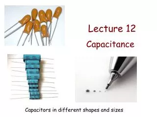
Lecture 12. Capacitance. Capacitors in different shapes and sizes. + Q. - Q. … separated by an insulator (dielectric). Can be air or vacuum . Capacitors. A capacitor is a device whose purpose is to store electric energy which can be released in a controlled manner.

Lecture 12
E N D
Presentation Transcript
Lecture 12 Capacitance Capacitors in different shapes and sizes
+Q -Q … separated by an insulator (dielectric).Can be air or vacuum. Capacitors A capacitor is a device whose purpose is to store electric energy which can be released in a controlled manner. Usually made of two conductorswith charges +Q and –Q…
Usually written as Capacitance: ΔV =V+ – V– Potential difference between the conductors V– V+ Symbol: +Q -Q Capacitance Units: Farad 1 F = 1 C/V
Can be considered infinite planes Example: Parallel plate capacitor Determine the capacitance of two parallel conducting large plates of area A separated by a small distance d. A d
0 0 Between the plates Let the plates have charges +Q and –Q. -Q Q
Capacitance of a parallel plate capacitor: Potential difference between the plates: The charge cancels out…
The capacitance of a system: • Does not depend on: • charge Q, • potential differenceΔV. (because ΔV is always proportional to Q) • Depends on: • the geometryof the system, • the dielectric between the conductors
- + C battery C → 2C Q → 2Q ACT: Variable capacitor A parallel plate capacitor is connected to a battery that produces a constant potential difference across its plates. If we push the plates of the capacitor together so that the distance between them is halved, the charge on the capacitor changes by: • ½ • B. 1 • C. 2 d → d/2 V constant Q = CV
d Current sensor Battery pressure oscillations Moveable plate Fixed plate oscillating plate separation d oscillating capacitance (C ~ 1/d) oscillating charge on plate (Q ~ C) oscillating current in wire (I = dQ/dt) DEMO: Variable capacitors oscillating electrical signal in sensor This is how microphones work! Current sensor Battery (fixed potential difference) Movable plate Fixed plate Sound waves incident
a b EXAMPLE: Spherical capacitor A capacitor is made of two concentric spherical metal shells of radii a and b. Find the capacitance of the system.
Gaussian surface: sphere of radius r (a < r < b ) a r b We need the potential difference between the spheres when they have charges Q and –Q. → we need the electric field in the region between the spheres. –Q +Q
Potential difference between the two spheres: Capacitance:
Example: Capacitance of a metal sphere of radius a DEMO: Maximum charge of a Van der Graaff Capacitance of a sphere One of the conductors in the capacitor can be (formally) at infinity (capacitor made of one conductor).
C2 C1 C3 A Ceq B A B Combination of capacitors Equivalent (or effective) capacitor Ceq (= “put all the capacitors inside a black box”) No measurement between A and B can distinguish the two circuits above.
A ● C2 C1 B ● Capacitors in series Two capacitors C1 and C2 are in series when they are connected one after the other:
Let a charge +Q1 enter through A and go to the top plate of C1. A charge -Q1 is induced on the bottom plate of C1. +Q1 This was initially an uncharged conductor -Q1 C2 C1 +Q2 -Q2 So +Q2 – Q1 = 0 or Q2 = Q1 Both capacitors are initially uncharged. A ● B ●
+Q2 +Q1 +Qe -Q2 Qe -Q1 And the equivalent capacitor? A ● C1 The charge introduced in the system must be the same: Q1 = Q2 = Qeq C2 B ● A ● +Qeq Ceq -Qeq B ●
A ● V1 = VA – VC C1 C ● V2 = VC – VB C2 Veq = VA – VB B ● A ● Ceq B ● Potential differences: Veq = V1 + V2
… C1 C2 C3 Use series connection to decrease capacitance Note that Capacitors in series: And remember that:
We have two conductors: top and bottom. Capacitors in parallel Two capacitors C1 and C2 are in parallel when the two plates of C1 are connected to the two plates of C2. A ● C2 C1 B ●
A ● Ceq B ● All points on the red conductor have potential VA. All points on the blue conductor have potential VB. A ● C2 C1 B ● = Veq (VA – VB) = V1 = V2
+Qe +Q2 +Q1 Qe -Q2 -Q1 Charges: A ● C1 C2 The charge introduced in the system must be the same: Q1 + Q2 = Qeq B ● A ● +Qeq Ceq -Qeq B ●
C2 C3 Use parallel connection to increase capacitance Note that Capacitors in parallel: … C1 … And remember that:
C1 C2 C3 C1 = 1.0 μF C2 = 2.0 μF C3 = 3.0 μF V0 = 12 V Example: Capacitor circuit For the circuit below, find: • The charge in C1 • The potential difference in C2
C1 C2 C3 C1 = 1.0 μF C2 = 2.0 μF C3 = 3.0 μF V0 = 12 V a. Q1 ?
C1 V0 = 12 V C2 C3 C1 = 1.0 μF C2 = 2.0 μF C3 = 3.0 μF [ [ ] ] b. V2 ?
ACT: Equivalent capacitance Which of the circuits has the largest capacitance? All capacitors are identical. A B D C Series connections decrease capacitance
B C A D
ACT: Car electrostatics You’re sick of getting shocked when you get out of the car... As you step out, what is the first part of the car that you should touch in order to minimize the shock? • The outside of the door. • B. The edge of the door • C. The window Glass is an insulator: Charges will flow in more slowly. Definitely not the edge of the door! The electric fields around a conductor are strongest near the pointy parts! (Ouch!)
ACT: Capacitors Which of the following capacitances can be achieved with series or parallel combinations of three 10 pF capacitors? • 3.33 pF • 6.66 pF • 15.0 pF • 30.0 pF • All of the above
C = 10.0 pF • 3.33 pF • 6.66 pF • 15.0 pF • 30.0 pF • All of the above
C = 10.0 pF • 3.33 pF • 6.66 pF • 15.0 pF • 30.0 pF • All of the above