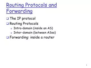
Download
1 / 83
830 likes | 947 Views
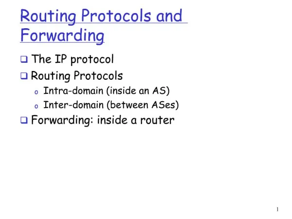
Chapter 1 Introduction to Routing and Packet Forwarding. CIS 82 Routing Protocols and Concepts Rick Graziani Cabrillo College graziani@cabrillo.edu Spring 2010. This Presentation. For detailed information see the notes section within this PowerPoint.

E N D
Chapter 1Introduction to Routing and Packet Forwarding CIS 82 Routing Protocols and Concepts Rick Graziani Cabrillo College graziani@cabrillo.edu Spring 2010
This Presentation • For detailed information see the notes section within this PowerPoint. • This presentation is based on the Exploration course/book, Routing Protocols and Concepts. • Notes section may contain additional details • For a copy of this presentation and access to my web site for other CCNA, CCNP, and Wireless resources please email me for a username and password. • Email: graziani@cabrillo.edu • Web Site: www.cabrillo.edu/~rgraziani
Note • This chapter contains mostly introductory material. • Most of not all of this information will be explained in more detail in later chapters or later courses. • The bootup process and the IOS are examined in a later course. • Do not worry or focus too much on the details for now. • This will all be examined and explained in the following chapters.
For further information • This presentation is an overview of what is covered in the curriculum/book. • For further explanation and details, please read the chapter/curriculum. • Book: • Routing Protocols and Concepts • By Rick Graziani and Allan Johnson • ISBN: 1-58713-206-0 • ISBN-13: 978-58713-206-3
Topics • CLI Configuration and Addressing • Implementing Basic Addressing Schemes • Basic Router Configuration • Building the Routing Table • Introducing the Routing Table • Directly Connected Networks • Static Routing • Dynamic Routing • Routing Table Principles • Inside the Router • Routers are computers • Router CPU and Memory • Internetwork Operating System • Router Bootup Process • Router Ports and Interfaces • Routers and the Network Layer • Path Determination and Switching Function • Packet Fields and Frame Formats • Best Path and Metrics • Equal Cost Load Balancing • Path Determination • Switching Function
Inside the Router Routers are computers Router CPU and Memory Internetwork Operating System Router Bootup Process Router Ports and Interfaces Routers and the Network Layer
Routers are Computers Leonard Kleinrock and the first IMP. • A router is a computer: • The first router (ARPANET): • IMP (Interface Message Processor) • Honeywell 516 minicomputer • August 30, 1969.
Routers forwarding packets (packet switching): • From the original source to the final destination. • Selects best path • A router connects multiple networks: • Interfaces on different IP networks
Router interfaces: • LAN • WAN
Routers Determine the Best Path • The router’s primary responsibility: • Determining the best path • Forwarding packets toward their destination
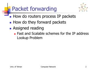
Routers Determine the Best Path IP Packet enters router’s Ethernet interface. Router examines the packet’s destination IP address. • Routing table • Determines best path. • Best match between destination IP address and network address in routing table Router searches for a best match between packet’s destination IP address and network address in routing table. Using the exit-interface in the route, the packet is forwarded to the next router or the final destination.
Router CPU and Memory • CPU - Executes operating system instructions • Random access memory (RAM) • running copy of configuration file • routing table • ARP cache • Read-only memory (ROM) • Diagnostic software used when router is powered up. • Router’s bootstrap program • Scaled down version of operating system IOS • Non-volatile RAM (NVRAM) • Stores startup configuration. (including IP addresses, Routing protocol) • Flash memory - Contains the operating system (Cisco IOS) • Interfaces - There exist multiple physical interfaces that are used to connect network. Examples of interface types: • Ethernet / fast Ethernet interfaces • Serial interfaces • Management interfaces
Cisco IOS - Internetwork Operating System • Manydifferent IOS images. • An IOS image is a file that contains the entire IOS for that router. • IOS features • Example IPv6 or a routing protocol such as Intermediate System–to–Intermediate System (IS-IS).
Bootup Process running-config startup-config IOS Bootup program IOS (running) ios (partial)
Where is the permanent configuration file stored used during boot-up? NVRAM (B) Where is the diagnostics software stored executed by hardware modules? ROM (D) Where is the backup (partial) copy of the IOS stored? ROM (D) Where is IOS permanently stored before it is copied into RAM? FLASH (C) Where are all changes to the configuration immediately stored? RAM (A) A B D C running-config startup-config IOS Bootup program IOS (running) ios (partial)
? ? ? ? ? ? ? running-config startup-config IOS Bootup program IOS (running) ios (partial)
B A D startup-config running-config Bootup program A C D IOS (running) IOS ios (partial) A B D C running-config IOS startup-config Bootup program IOS (running) ios (partial)
Router Boot Process – Details (later) 1. ROM 1. POST 2. Bootstrap code executed 3. Check Configuration Register value (NVRAM) 0 = ROM Monitor mode 1 = ROM IOS 2 - 15 = startup-config in NVRAM 2. Check for IOS boot system commands in startup-config file (NVRAM) If boot system commands in startup-config a. Run boot system commands in order they appear in startup-config to locate the IOS b If boot system commands fail, use default fallback sequence to locate the IOS (Flash, TFTP, ROM) 3.Locate and load IOS, Default fallback sequence: No IOS boot system commands in startup-config a. Flash (sequential) b. TFTP server (netboot) - The router uses the configuration register value to form a filename from which to boot a default system image stored on a network server. c. ROM (partial IOS) or keep retrying TFTP depending upon router model - If no IOS located, get partial IOS version from ROM 4.Locate and load startup-configconfiguration a. If startup-config found, copy to running-config b. If startup-config not found, prompt for setup-mode c. If setup-mode bypassed, create a “skeleton” default running-config (no startup-config)
Verify the router boot-up process • show version command is used to view information about the router during the bootup process (later).
Ports and Interfaces • Port - management ports used for administrative access • Interface - capable of sending and receiving user traffic. • Note: However, these terms are often used interchangeably.
Management Ports Console port • Terminal • PC running terminal emulator software • No need for network access • Used for initial configuration Auxiliary (AUX) port • Not all routers have auxiliary ports. • At times, can be used similarly to a console port • Can also be used to attach a modem. • Note: Auxiliary ports will not be used in this curriculum.
Router Interfaces • Interfaces - Receive and forward packets. • Various types of networks • Different types of media and connectors. • Different types of interfaces. • Fast Ethernet interfaces - LANs • Serial interfaces - WAN connections including T1, DSL, and ISDN
Router Interfaces FastEthernet 0/0 MAC: 0c00-41cc-ae12 10.1.0.1/16 FastEthernet 0/0 MAC: 0c00-3a44-190a 192.168.1.1/24 • Router Interface: • Different network • IP address and subnet mask of thatnetwork • Cisco IOS will not allow two active interfaces on the same router to belong to the same network. Serial 0/0 Serial 0/1 172.16.1.1/24 172.16.1.2/24
LAN Interfaces • Ethernet and Fast Ethernet interfaces • Connects the router to the LAN • Layer 2MAC address • Participates in the Ethernet • Address Resolution Protocol (ARP): • Maintains ARP cache for that interface • Sends ARP requests when needed • Responds with ARP replies when required • Typically an RJ-45 jack (UTP). • Router to switch: straight-through cable • Router to router: crossover cable
WAN Interfaces • Point-to-Point, ISDN, and Frame Relay interfaces • Connects routers to external networks. • The Layer 2 encapsulation can be different types including: • PPP • Frame Relay • HDLC (High-Level Data Link Control). • Note: MAC addresses are used only on Ethernet interfaces and are not on WAN interfaces. • Layer 2 WAN encapsulation types and addresses are covered in a later course.
Routers at the Network Layer • Layer 3 device because its primary forwarding decision is based on the information in the Layer 3 IP packet (destination IP address). • This is known as routing.
Ethernet Frame IPv4 (Internet Protocol) • Layer 2 addresses: Addressing PC/Router-to-PC/Router within a network • Layer 3 addresses: • Original source layer 3 address (IP) to final destination layer 3 address (IP) • Does not change (unless NAT is used)
Best Path Which is path is my “best path”? RIP’s metric is hop count ? OSPF’s metric is bandwidth • Router’s determine best-path to a network: • Depends on the routing protocol • A protocol used to between routers to determine “best path” • Routing protocols use their own rules and metrics. • A metric: • Quantitative value used to measure the distance to a given route. • Best path: • Path with the lowest metric.
Equal Cost Load Balancing To reach the 192.168.1.0/24 network it is 2 hops via R2 and 2 hops via R4. ? ? 192.168.1.0/24 What happens if a routing table has two or more paths with the same metric to the same destination network? (equal-cost metric) Router will perform equal-cost load balancing.
Equal-Cost Paths Versus Unequal-Cost Paths ? T1 ? T3 192.168.1.0/24 Can a router use multiple paths if the paths (cost, metric) to reach the destination network are not equal? EIGRP routing protocol which supports unequal cost load balancing
Packet Forwarding Packet forwarding involves two functions: • Path determination function • Switching function
Path Determination Router receives packet. Destination IP address matches a network on one of its directly connected networks. Packet is forwarded out that network. Directly connected network • Path determination function is the process of how the router determines which path to use when forwarding a packet. • Router searches its routing table for match with packet’s destination IP address. • One of three path determinations results from this search: • Directly connected network • Remote network • No route determined
Path Determination Router receives packet. Destination IP address matches a remote network which can only be reached via another router. Packet is forwarded out that network to the next-hop router. Remote network
Path Determination Router receives packet. Destination IP address does NOT match any network in the router’s routing table. Packet is dropped. No route determined Does this mean the network does not exist? No, only that the router does not know about that network. (later)
Packet Forwarding: Switching Function • Switching function is the process used by a router to: • Accept a packet on one interface and • Forward it out another interface • Encapsulate the packet in the appropriate data-link frame type for the outgoing data link.
192.168.4.10 Path Forwarding 192.168.1.10 Layer 2 Data Link Frame Layer 3 IP Packet What does a router do with a packet received from one network and destined for another network? • Decapsulates the Layer 3 packet by removing the Layer 2 frame header and trailer • Examines the destination IP address of the IP packet to find the best path in the routing table • Encapsulates the Layer 3 packet into a new Layer 2 frame and forwards the frame out the exit interface
Remember: Encapsulation These addresses do not change! Layer 3 IP Packet These change from host to router, router to router, and router to host. Layer 2 Data Link Frame • Now, let’s do an example… Current Data Link Address of Host or Router’s exit interface Next hop Data Link Address of Host or Router’s interface
Layer 2 Data Link Frame Layer 3 IP Packet • This is just a summary. • The details will be shown next! • Now for the details…
Layer 2 Data Link Frame Layer 3 IP Packet
Layer 2 Data Link Frame Layer 3 IP Packet
Layer 2 Data Link Frame Layer 3 IP Packet
Layer 2 Data Link Frame Layer 3 IP Packet
Layer 2 Data Link Frame Layer 3 IP Packet
Layer 2 Data Link Frame Layer 3 IP Packet • The summary once again!
CLI Configuration and Addressing Before we begin: • Download: Packet Tracer File: • http://netacad.cabrillo.edu/curriculum/graziani/cis82/labs-e2/e2-1-5-2.pkt • Download and Install Packet Tracer you have not done so already: • http://www.cabrillo.edu/~rgraziani/courses/cis81.html • Download Lab: • http://netacad.cabrillo.edu/curriculum/graziani/cis82/labs-e2/en_ERouting_ILM_v4050.pdf
Hands-on Labs NetLab Networking Lab: Room 2504 and CTC Packet Tracer (Not for homework) Check-out Pods