MEMBRANE PROCESSES
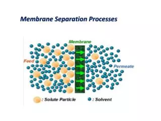
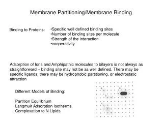
MEMBRANE SEPARATION. MEMBRANE PROCESSES. PRESSURE DRIVEN MEMBRANE PROCESS. Various pressure-driven membrane process can be used to : . 1. Concentrate . 2. Purify a dilute (aqueous or non aqueous). THE PARTICLE OR MOLECULAR SIZE AND CHEMICAL PROPERTIES of solute DETERMINE : .

MEMBRANE PROCESSES
E N D
Presentation Transcript
MEMBRANE SEPARATION MEMBRANE PROCESSES
PRESSURE DRIVEN MEMBRANE PROCESS Various pressure-driven membrane process can be used to : 1. Concentrate 2. Purify a dilute (aqueous or non aqueous) THE PARTICLE OR MOLECULAR SIZE AND CHEMICAL PROPERTIES of solute DETERMINE : Structure of membrane 1. Pore size 2. Pore size distribution PORE SIZE
Various PROCESS CAN BE DISTINGUISH RELATED TO THE PARTICLE SIZE OF THE SOLUTE AND CONSEQUENTLY TO MEMBRANE STRUCTURE :
Various PROCESS CAN BE DISTINGUISH RELATED TO THE PARTICLE SIZE OF THE SOLUTE AND CONSEQUENTLY TO MEMBRANE STRUCTURE :
MICROFILTRATION Is the membrane process which most closely resembles conventional coarse filtration. 10 – 0,05 m Pore size: Suitable for retaining suspensions and emulsions The Darcy’s Law : Where the permeability constant A contains structural factors such as the porosity and pore size (pore size distribution) For laminar convective flows through a porous systems : Where r is the pore radius, Δx is the membrane thickness, η is he dynamic viscosity and is the tortuosity factor ehich is unity in the case of cylindrical pores.
MEMBRANE FOR MICROFILTRATION Can be prepared from organic materials (polymers) and inorganic (ceramics, metals, glasses) Various techniques can be employed : 1. Sintering 2. Stretching 3. Track - etching 4. Phase inversion Frequently, inorganic membranes are used instead of polymeric membranes because of their outstanding chemical and thermal resistances. POROSITIES AND PORE SIZE DISTRIBUTION
These various techniques allow to prepare microfiltration membranes from virtually all kinds of materials of which polymers and ceramics are the most important. • Polytetrafluoroethylene (PTFE) • Poly(vinylidene fluoride) (PVDF) • Polyproylene (PP) • Polyethylene (PE) HYDROPHOBIC POLYMERIC MEMBRANES • Cellulase esters • Polycarbonate (PC) • Aliphatic polyamide (PA) • Polyetheretherketone (PEEK) HYDROPHILIC POLYMERIC MEMBRANES • Alumina (Al2O3) • Zirconia (ZrO2) • Titania (TiO2) • Silicium carbide (SiC) CERAMIC MEMBRANES
MAIN PROBLEMS of MICROFILTRATION Deposition of solute inside the pores of membrane or membrane surface Concentration polarization and fouling FLUX DECLINE NEED Careful control over the mode of process operation NEED Must be cleaned periodically
TWO MODES OF FILTRATION: DEAD END FILTRATION The feed flow is perpendicular to the membrane surface, so that the retained particles accumulate and form a type of a cake layer at the membrane surface. The thickness of the cake increases with filtration times and consequently the permeation rate decreases with increasing cake layer thickness CROSS FLOW FILTRATION The feed flow is along the membrane surface, so that part of the retained solutes accumulate
INDUSTRIAL APPLICATIONS • Cold sterilization of beverages and pharmaceutical • Cell harvesting • Clarification of fruit juice, wine and beer • Ultrapure water in the semiconductor industry • Metal recovery as colloidal oxides or hydroxides • Waste-water treatment • Continuous fermentation • Separation of oil-water emulsions
ULTRAFILTRATION Is a membrane process whose nature lies between nanofiltration and microfiltration 0,05 m – 1 NM Pore size: UF is typically used to retain macromolecules and colloids from a solution. UF and MF can both be consider as porous membrane where rejection is determined by the size and shape of the solutes relatives to the pore size in the membrane and where the transport of solvent is directly proportional to the applied pressure. In fact both UF and MF involve similar membrane processes based on the same separation principle. However, an important difference is that UF membrane have an asymmetric structure with a much denser top layer (small pore size and lower surface porosity) and consequently a much higher hydrodynamic resistance.
MEMBRANE FOR ULTRAFILTRATION Most of UF membrane used commercially these day are prepared from : POLYMERIC MEMBRANES • Polytetrafluoroethylene (PTFE) • Poly(vinylidene fluoride) (PVDF) • Polyacrylonitrile • Polyimide • Polyetheretherketone • Aliphatic polyamides • Cellulosics BY PHASE INVERSION PROCESS INORGANIC (CERAMIC) • Alumina (Al2O3) • Zirconia (ZrO2) SOL GEL TECHNIQUE
APPLICATIONS • Recovery of whey proteins • Recovery of potato starch and proteins • Concentration of egg product • Clarification of fruit juices and alcoholic beverages 1 FOOD AND DAIRY INDUSTRY 2 PHARMACEUTICAL INDUSTRY 3 METALLURGY CHEMICAL INDUSTRY 4 TEXTILE INDUSTRY 5 6 LEATHER INDUSTRY 7 PAPER INDUSTRY
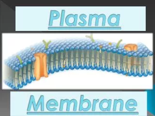
REVERSE OSMOSIS AND NANOFILTRATION RO and NF are used when low molecular weight solutes such as inorganic salts or small organic mocules such as glucose, and sucrose have to be separated from solvent. PRINCIPE OF REVERSE OSMOSIS FORCE The membrane is permeable to the solvent (water) but not to the solute (salt). In order to allow water to pass through the membrane, the applied pressure must be higher than the osmotic pressure. Salt solution Membrane “Complete barrier to dissolved salt” Pure water
The pressure used in reverse osmosis range from 20 – 100 bar and in nanofiltration from about 10 – 20 bar, which much higher than those used in ultrafiltration Both process are considered as one process since the basic principles are the same. NF membranes are the same as RO membranes only the network structure is more open. Comparison of retention characteristic between nanofiltration (NF) and reverse osmosis (RO) are listened :
MEMBRANES FOR RO AND NF • The flux is approximately inversely proportional to the membrane thickness and for this reason most reverse osmosis membranes have an asymmetric structure with a thin dense toplayer (thickness ≤ 1um) supported by a porous sublayer (thickness 50 – 150 um) • The resistance towards transport being determined mainly by the dense toplayer. • An asymmetric membrane structure can be distinguished: (i) integral asymmetric membranes, and (ii) composite membranes.
Integral Asymmetric Membranes Both toplayer and sublayer consists of the same material. These membrane are prepare by phase inversion technique. The polymeric material from which the membrane it to be prepared is soluble in a solvent or a solvent mixture. 1 cellulose esters. This materials are very suitable for desalination because of their high permeability towards water in combination with a (very) low solubility towards salt. An important class of asymmetric membranes are : 2 Aromatic polyamides. These material also show high selectivities towards salts but their water flux is somewhat lower. 3 Polybenzimidazoles, polybenzimidazolones, polyamidedehydrazide, and polyimides
Composite Membranes The second type of structure frequently used in RO while most of the NF membrane are in fact composite membrane. In such membranes the top layer and sublayer are composed of different polymeric materials so that each layer can be optimized separately. • The first stage is the are preparation of the porous sublayer. Important criteria for this sublayer are surface porosity and pore size distribution and asymmetric ultrafiltration membranes are often used. Different methods have been employed for placing a thin dense layer on top of this sublayer : • dip coating • Interfacial polymerization • Plasma polymerization
APPLICATION RO • purification water, desalination of brackish and seawater to produce potable water • Production of ultrapure water for the semiconductor industry • Concentration step particularly in the food industry ( concentration of fruit juice) • Galvanic industry (concentration of waste stream) • Dairy industry (concentration of milk to prior cheese manufacture) NF • When a high retention is required for NaCl with high feed concentrations reverse osmosis reverse osmosis is the preferred process. In other cases with much lower concentrations, divalent ions and micro solutes with molecular weight nanofiltration is the preferred process. Since the water permeability is (much) higher in nanofiltration the capital cost for a certain application will be lower.