Download
1 / 9
90 likes | 200 Views
C.1 Network Design in Support of DARPA’s Control Based MANET. THIS IS A JOINT EFFORT WITH MARTIN LOCKHEED (ATL).

E N D
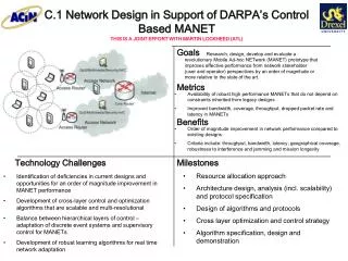
C.1 Network Design in Support of DARPA’s Control Based MANET THIS IS A JOINT EFFORT WITH MARTIN LOCKHEED (ATL) Research, design, develop and evaluate a revolutionary Mobile Ad-hoc NETwork (MANET) prototype that improves effective performance from network stakeholder (user and operator) perspectives by an order of magnitude or more relative to the state of the art. Availability of robust high performance MANETs that do not depend on constraints inherited from legacy designs Improved bandwidth, coverage, throughput, dropped packet rate and latency in MANETs Order of magnitude improvement in network performance compared to existing designs Criteria include: throughput, bandwidth, latency, geographical coverage, robustness to interference and jamming and mission longevity Resource allocation approach Architecture design, analysis (incl. scalability) and protocol specification Design of algorithms and protocols Cross layer optimization and control strategy Algorithm specification, design and demonstration Identification of deficiencies in current designs and opportunities for an order of magnitude improvement in MANET performance Development of cross-layer control and optimization algorithms that are scalable and multi-resolutional Balance between hierarchical layers of control – adaptation of discrete event systems and supervisory control for MANETs Development of robust learning algorithms for real time network adaptation
C.2 Common Spectrum Management Tool THIS PROJECT IS A JOINT EFFORT WITH LOCKHEED MARTIN (ATL) IN SUPPORT OF 2005 EUCOM Provide core technology required to conduct spectrum management in battlefield environments Provide a modular structured Spectrum Management capability Frequency availability and conflict free usage fraction as compared to the currant state of the art Availability of easy to use user-friendly interface for real time use by communications/signal officers in the field Improved ability to plan and manage the usage of the electromagnetic spectrum Ensure spectrum availability and minimize resource shortfalls Urban area daily activity in the 2.4 GHz band during the week (percentage of time above minus 98 dBm ((Biggs et al., 2004) Provide for planning, management and implementation of spectrum in one tool Provide intuitive interface/visualization for easy interpretation of spectrum needs Develop spectrum planning repository Enable enhanced spectrum access across the battlefield Develop urban propagation models for understanding and prediction of spectrum management and availability Develop a CES unit for plan evaluation Develop automated registration, assignment and de-confliction algorithms for shared use
C.3 Sensor Network for Urban Nuclear, Biological, and Chemical (NBC) Fallout Propagation Prediction Develop a sensor network planning tool that will allow for defense against nuclear, biological, and chemical attacks in a dense urban environment • Sensor network design for minimized population consumption of NBC contaminants • High connectivity and robust sensor network communication links Sensor Network Illustration of NBC release and contaminant response in a dense urban environment Sensor network for defense against NBC attacks and development of a tool for terrorist attack recovery and response • Develop modeling software and visualization modules of NBC fallout propagation in a dense urban environment given prevailing wind data • Fuse sensory data and propagation model data to determine near-optimal sensor location given potential terrorist targets and practical sensor placement constraints • Develop real-time propagation visualization program for rescue worker use • Develop self-organization, recovery, and healing of the sensor array in the face of massive damage, islanding, and catastrophic damage to surrounding infrastructure • Software model for propagation prediction and sensor network design in any urban environment • Data fusion to integrate sensor data for sensor network design and NBC attack source localization • Visualization and control modules that allows for real-time propagation display and network design • Design of physical and protocol layer for sensor-to-sensor and sensor-to-soldier terminal communication link
C.4 MIMO Ad Hoc Battlefield Networks in Dense Urban Environments Design, develop, simulate, prototype, test and evaluate a set of energy efficient signal processing and protocol control algorithms for military MIMO (Multi- Input Multiple Output) radio systems. Improved throughput, latency and dropped packet performance in wireless networks operating in harsh environments Spatial diversity improves reliability and throughput of links in non-line-of-sight propagation. Spatial degrees of freedom allow for significant interference suppression. Improved resilience to jamming. Computational Electromagnetic Simulation of an Ad-Hoc Network Operating in an Urban Environment • Design, simulate, prototype and test advanced signal processing and protocol control algorithms for the MIMO channel environment (up to and including an 8x8 configuration) including : • Real Time Channel Estimation • Advanced Modulation/Demodulation techniques for energy efficient MIMO • Advance Coding and Forward Error Control (FEC) • Physical Layer Multicast for the MIMO environment • Cross layer physical/data link interaction • Cross channel interference Channel estimation algorithms Energy efficient time space coding MIMO aware MAC algorithm MIMO ad-hoc testbed: design and fabricate four (4) programmable radio nodes to support and demonstrate advanced energy aware algorithms. The RF channels and software capability shall be consistent with the developing JTRS Cluster 5 radio and the Soldier Radio Waveform.
C.5 Multiple Input Multiple Output (MIMO)-Enhanced Free Space Optical Communications Apply existing MIMO techniques for RF signals to VCSEL arrays to increase the spectral efficiency of the communication link, by using misalignments and optical crosstalk, detrimental to conventional free space optical communications, to create multiple signal paths Formulate the VCSEL array in terms of the MIMO matrix channel and perform an analysis of existing space-time communication techniques to determine what kind of signaling would be most efficient Channel Capacity BER Increased Channel Capacity Spatial degrees of freedom overcome optical crosstalk and misalignment. Support ARL Optical Backplane Project (sponsored through AMRDEC) and Missile ATR systems. Real Time Channel Estimation Advanced Modulation/Demodulation techniques for energy efficient MIMO Cross layer physical/data link interaction Cross channel interference Hardware validation An experimental testbed, demonstrating VCSEL array to array communication Survey of MIMO signaling techniques and their ability to address the unique challenges of free space optical communications Models of the detrimental effects caused by practical alignment and sensitivity issues of VCSEL arrays Hardware demonstration of the ability of MIMO signaling techniques to improve communication between VCSEL arrays Results of field-tests in practical operational environments
C.6 Hybrid RF & Free-Space Diffuse Optical MIMO LAN Communications Construct a MIMO software defined hardware testbed with the ability to “plug-in” diffuse optical transceivers while also allowing for hybrid, simultaneous use of multiple modalities (diffuse optical and radio frequency). Demonstrate a proof of concept field demonstration and theoretical design of hybrid diffuse optical-RF MIMO communication links for DARPA THOR and ORACLE programs Next generation LAN transceivers supporting hybrid communication of diffuse optical signals and RF signals using MIMO and space-time coding algorithms Channel Capacity Compare with current RF systems Provide high throughput wireless links with interference levels far below the current state-of-the-art radio frequency (RF) systems Provide increased data rates, robustness, security, and connectivity in channels inaccessible to RF Improved resilience to jamming. Highly secure communication, low probability of intercept Real Time Channel Estimation Advanced Modulation/Demodulation techniques for energy efficient MIMO Transceiver array geometry and design Space time coding algorithms and protocol Cross layer physical/data link interaction Cross channel interference Hardware validation Develop Channel and interference models for diffuse optical-MIMO communications. Provide unified theory for allocating resources (such as power and rate) to hybrid modality LAN through application of utility and pricing functions from game theory. Build/Acquire Diffuse Optical Transceivers Characterization of Optical MIMO Hardware Channel and Interference Design of Utility and Pricing Functions for Diffuse Optical and RF Modalities RF + Diffuse Optical Construction and Testing RF + Diffuse Optical Networking
C.7 High-Resolution Imaging Sensor Network New design paradigm for a sensor and sensor network that utilizes state-of-the-art optical MEMS technology to produce ultra-high resolution images. Introduce into the optics of the sensor a micromirror array, which may change state thousands to millions of times per second. System Field of View Resolution and creation speed of images Surveillance in the field or in a already cleared building for unmanned monitoring Imaging sensors would placed in a small network High resolution images of environment changes, as well as the location, would be sent back to a command node. This project uses Lucent Lambda Router MEMS micromirror (seen packaged in 16x16 array and a SEM picture of a mirror) to produce high resolution images for a surveillance imaging network Surveillance image reconstructed from thousands of images from each of the micromirrors in the array Use of the shelf MEMS (currently using Lucent Lambda Router mirrors) Expand the Field of View (FoV) of the sensor Frame rate and speed of image construction Network routing and protocol development Simulation of theory Acquire and characterize MEMS mirror array Obtain data from individual mirrors and reconstruct surveillance image Development of network routing protocol Integration of MEMS, power, CCD, processor, and networking Test and demonstration
C.8 Adaptable Low-Light and Multi-Wavelength Imaging Sensor Network Use coded-aperture imaging to provide low light imaging and imaging non-visible wavelengths Use TI’s MEMS for reconfigurable apertures for changing enviroments Image resolution, clarity, and contrast Low-light applications Imaging of non-visable wavelengths Surveillance in the field or in a already cleared building for unmanned monitoring Imaging sensors would placed in a small network High resolution images of environment changes, as well as the location, would be sent back to a command node. Reconfigurable multi-aperture configuration (provided by MEMS mirror array) provides low-light and non-visible imaging Use of TI’s DMD mirrors for new application Determine appropriate coded aperture algorithms for construction of aperture and decomposition of image Capture CCD image from the TI DMD device Integration to sensor network Coded aperture algorithms for aperture plane and reconstruction of image Simulation of theory Obtain MEMS mirror array, CCD camera and other hardware Development of network routing protocol Integration of MEMS, power, CCD, processor, and networking Test and demonstration
C.9 Alignment and Packaging of Opto-Electronic Sensors and Systems Automate the assembly, manufacturing, and packaging process for optoelectronic sensors and systems Use advanced device specific optical power models as well as intelligent control theory to yield high performance, low cost packaging Power efficiency of the system Robustness of the packaged sensor/system System Performance in terms of BER, insertion loss Intelligent alignment and packaging provide better system performance Packaged system is more robust Optical models for knowledge based control Automation equipment to align and package state of the art opto-electronic devices and systems (as seen on the right) for maximum performance Modeling of optical system for knowledge based control Determination of inverse model from the optical model to be placed in feed-forward control loop Linearization of non-linear optical models for model learning Identify the needs for Army applications Incorporation of feed-forward control loop Incorporation of learning loop Provide robust connection Report of optoelectronic alignment and packaging needs in the Army Develop optical models based on Rayleigh-Sommerfeld formulation Expand on learning algorithms for our application Identify test device/systems and measure current system performance when packaged Incorporate our technique for comparison