11. I/O Systems
11. I/O Systems. 11.1 Basic Issues in Device Management 11.2 A Hierarchical Model 11.3 I/O Devices 11.4 Device Drivers Memory-Mapped vs Explicit Device Interfaces Programmed I/O with Polling Programmed I/O with Interrupts Direct Memory Access (DMA) 11.5 Device Management

11. I/O Systems
E N D
Presentation Transcript
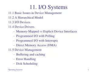
11. I/O Systems 11.1 Basic Issues in Device Management 11.2 A Hierarchical Model 11.3 I/O Devices 11.4 Device Drivers • Memory-Mapped vs Explicit Device Interfaces • Programmed I/O with Polling • Programmed I/O with Interrupts • Direct Memory Access (DMA) 11.5 Device Management • Buffering and caching • Error Handling • Disk Scheduling
Basic Issues • I/O devices: • Communication devices • Input only (keyboard, mouse, joystick, light pen) • Output only (printer, visual display, voice synthesizers…) • Input/output (network card…) • Storage devices • Input/output (disk, tape, writeable optical disks…) • Input only (CD-ROM…)
Basic Issues • Every device type/model is different • input/output/both, block/char oriented, speed, errors, … • Main tasks of I/O system: • Present logical (abstract) view of devices • Hide details of hardware interface • Hide error handling • Facilitate efficient use • Overlap CPU and I/O • Support sharing of devices • Protection when device is shared (disk) • Scheduling when exclusive access needed (printer)
I/O System Interface • Block-Oriented Device Interface • direct access • contiguous blocks • usually fixed block size • Operations: • Open: verify device is ready, prepare it for access • Read: Copy a block into main memory • Write: Copy a portion of main memory to a block • Close: Release the device • Note: these are lower level than those of the FS • Used by File System and Virtual Memory System • Applications typically go through the File System
I/O System Interface • Stream-Oriented Device Interface • character-oriented • sequential access • Operations: • Open: reserve exclusive access • Get: return next character of input stream • Put: append character to output stream • Close: release exclusive access • Note: these too are different from those of the FS but some systems try to present a uniform view of files and devices
I/O System Interface • NetworkInterface • key abstraction:socket • endpoints of a “line” between two processes • once established, use protocol to communicate • Connection-lessprotocols • send messages, called datagrams • Operations: send, receive (to/from sockets) • Connection-based protocols • establish a connection called virtual circuit • Operations:connect, accept, read, write
I/O Devices – Output • Display monitors • character or graphics oriented • Different data rates: • 25 x 80 characters vs 800 x 600 pixels (1B allows 256 colors) • Refresh 30-60 times/s for video • Printers(ink jet, laser) • Interface • write to controller buffer • wait for completion • handle errors
I/O Devices – Input • Keyboards • most common: “QWERTY” • Pointingdevices • Mouse • Trackball • Joystick • Scanners • Interface • device generates interruptwhen data is ready • read data from controller buffer • low data rates, not time-critical
I/O Devices – Storage • Disks • Surface, tracks/surface, sectors/track, bytes/sector • All sectors numbered sequentially 0..(n-1) (device controller provides mapping)
I/O Devices – Storage • Track skew • Account for seek-to-next-track to minimize rotational delay
I/O Devices – Storage • Double-sided or multiple surfaces • Tracks with same diameter =cylinder • Sectors are numbered within cylinder consecutively to minimize seek time
I/O Devices – Storage • Optical disks • CD-ROM, CD-R (WORM), CD-RW • Originally designed for music • Data stored as continuousspiral,subdivided into sectors • Higher storage capacity: 0.66 GB/surface • Constant linear speed (200-530 rpm), high data rate
I/O Devices – Storage • Critical issue: data transfer rates of disks • Sustained rate:continuous data delivery • Peek rate:transfer once read/write head is in place • depends on rotation speed and data density • Example: 7200 rpm, 100 sectors/track, 512 bytes/sector. What is the peak transfer rate? • 7200 rpm: 60,000/7200=8.3 ms/rev • 8.3/100 = 0.083 ms/sector • 512 bytes transferred in 0.083 ms: ~6.17 MB/s What is the Sustained rate?–Depends on file organization
Device Drivers • accept command from application • get/put character • read/write block • send/receive packet • interact with device controller (hardware) to carry out command • driver-controller interface: set of registers
Device Drivers: Interface to Controller • How does driver read/write registers? • Explicit: special I/O instruction: • io_store • cpu_reg, • dev_no, • dev_reg • Memory-mapped:CPU instruction:store cpu_reg, n • (n is memory • address)
Programmed I/O with Polling • Who moves the data? • How does driver know when device is ready? • CPU is responsible for • movingevery character to/from controller buffer • detectingwhen I/O operation completed • Protocol to input a character/block:
Programmed I/O with Polling • Driver operation to input sequence of characters or blocks: i = 0; do { write_reg(opcode, read); while (busy_flag == true) {…??...}; //waiting mm_in_area[i] = data_buffer; increment i; compute; } while (…)
Programmed I/O with Polling • Driver operation to output sequence of characters or blocks: i = 0; do { compute; data_buffer = mm_out_area[i]; increment i; write_reg(opcode, write); while (busy_flag == true) {…??...}; } while (data_available)
Programmed I/O with Polling • What to do while waiting? • Idle (busy wait) • Some other computation (what?) • How frequently to poll? • Giveup CPU • Device may remain unused for a long time • Data may be lost
Programmed I/O with Interrupts • CPU is responsible for moving data, but • Interrupt signal informs CPU when I/O operation completes • Protocol to input a character/block:
Programmed I/O with Interrupts • Compare Polling with Interrupts: i = 0; do { write_reg(opcode, read); while (busy_flag == true) {…}; //active wait mm_in_area[i] = data_buffer; increment i; compute; } while (…) i = 0; do { write_reg(opcode, read); block to wait for interrupt; mm_in_area[i] = data_buffer; increment i; compute; } while (…)
Programmed I/O with Interrupts • Example:Keyboard driver do { block to wait for interrupt; mm_in_area[i] = data_buffer; increment i; compute(mm_in_area[]); } while (data_buffer != ENTER) • Note: • there is no write_reg command, pressing a key generates interrupt • compute depends on type of input: raw/cooked • E.g. trying to type “text” but with typos raw: t e s t ← BS x → cooked: t e x t
Programmed I/O with Interrupts • I/O with interrupts: more complicated, involves OS • Example: sequence of reads • More overhead (OS) but better device utilization
Direct Memory Access (DMA) • CPU does not transfer data, only initiates operation • DMA controller transfers data directly to/from main memory • Interruptswhen transfer completed • Input protocol:
DMA • Driver (CPU) operation to input sequence of bytes: write_reg(mm_buf, m); // give parameters write_reg(count, n); write_reg(opcode, read); // start op block to wait for interrupt; • Writing opcode triggers DMA controller • DMA controller issues interrupt after n chars in memory • Cycle Stealing • DMA controller competes with CPU for memory access • generally not a problem because: • Memory reference would have occurred anyway • CPU is frequently referencing data in registers or cache, bypassing main memory
Device Management • Device-independent techniques: • Buffering/caching • Error Handling • Device Scheduling/Sharing
Buffering • Reasons for buffering • Allows asynchronous operation of producers and consumers • Allows different granularities of data • Consumer or producer can be swappedout while waiting for buffer fill/empty
Buffering • Single buffer operation • Double buffer (buffer swapping) • Increases overlap • Ideal when: time to fill = time to empty = constant • When times differ, benefits diminish
Buffering • Circular Buffer (bounded buffer from Ch. 2) • Producer and consumer each use an index • nextin gives position of next input • nextout gives position of next output • Both are incremented modulo n at end of operation • When average times to fill/empty are comparable but vary over time: circular buffer absorbs bursts • Buffer Queue • Variable size buffer to prevent producer blocking • Implement as linked list – needs dynamic memory management • Buffer Cache: pool of buffers for repeated access
Error Handling • Types of error • Persistent vs Transient • SW vs HW • PersistentSW error • Repair/reinstall program • TransientSW/HW errors: • Error detecting/correcting codes • e.g., Hamming code (separate lecture) • Retry operation, e.g. disk seek/read/write • Persistent HW errors: • Redundancy in storage media
Bad block detection/handling • Block may be bad as a manufacturing fault or during use • Parity bit is used to detect faulty block • The controller bypasses faulty block by renumbering • A spare block is used instead • Two possiblere-mappings: • simple • preserves contiguityof allocation
Stable storage • Some applications cannot tolerate any loss of data (even temporarily) • Stable storage protocols: • Use 2 independent disks, A and B • Write: write to A; if successful, write to B; if either fails, go to recovery • Read: read from A and B; if A!=B, go to Recovery • Recovery from Media Failure:A or B contains correct data (parity); remap failed disk block • Recovery from Crash: • if while reading, just repeat the read • if while writing A, B is correct; if while writing B, A is correct; recover from whichever is correct
RAID • RAID = Redundant Array of Independent Disks • Increased performance through parallel access • Increased reliability through redundant data • Maintain exact replicas of all disks • most reliable but wasteful • Maintain only partial recovery information • (e.g. error correcting codes)
Device Management • Disk Scheduling • Requests for different blocks arrive concurrently from different processes • Minimize rotational delay: • re-order requests to blocks on each track to access in one rotation • Minimize seektime: • Conflicting goals: • Minimize total travel distance • Guarantee fairness
Device Management • Algorithms • FIFO: requests are processed in the order of arrival • simple, fair, but inefficient • SSTF (Shortest Seek Time First): always go to the track that’s nearest to the current positions • most efficient but prone to starvation • Scan (Elevator): • maintain a direction of travel • always proceed to the nearest track in the current direction of travel • if there is no request in the current direction, reverse direction • fair, acceptable performance
Device Management Example: assume moving from 0 to 5; then 12,4,7 arrive