Download
1 / 1
10 likes | 129 Views
V. A Grid Compatible Methodology for Reactive Power Compensation in Renewable Based Distribution System. I R. X T. Tareq Aziz, U. P. Mhaskar , Tapan K. Saha, N. Mithulananthan School of Information Technology and Electrical Engineering, The University of Queensland, Australia. V DC.

E N D
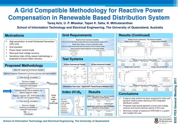
V A Grid Compatible Methodology for Reactive Power Compensation in Renewable Based Distribution System IR XT Tareq Aziz, U. P. Mhaskar, Tapan K. Saha, N. Mithulananthan School of Information Technology and Electrical Engineering, The University of Queensland, Australia VDC Motivations Results (Continued) Grid Requirements Voltage recovery requirement : Time Domain simulation Reactive Power Generation Capability • High penetration of small Distributed Generation (DG) units • Grid standard • Power-factor control mode • Slow post-fault voltage recovery • Sensitivity index dV/dIR based methodology is proposed to ensure faster recovery Voltage at Bus 3 with DG1 Voltage at Bus 6 with DG2 • IEEE Std 1547-2003 does not allow DG units to actively regulate voltage at PCC. Steady State Voltage, Continuous Operation range • DG bus voltage should remain within the range of ±10% of nominal voltage. Interconnection System Response to Abnormal Voltage Test Systems Voltage recovery time for 16 Bus System Proposed Methodology 16 Bus Commercial Feeder 43 Bus Industrial Feeder Voltage at Bus 4 with DG1 Voltage at Bus 50 with DG2 Take DG integrated Distribution System Optimal Capacitor Placement to minimize grid loss with load variation Time domain simulation Dynamic Voltage restoring compatibility to meet grid requirement Yes Complete Voltage recovery time for 43 Bus System Simulation Tool used : DigSILENT PowerFactory Release 14.0 No New Index Calculate dV/dIR and its direction for optimal capacitor nodes Index dV/dIR Results Conclusions Check next location for STATCOM Replace capacitor with STATCOM on the bus with most negative dV/dIR Steady State requirement: Optimal Capacitor Solution for 16 Bus System • A step by step method has been proposed for static and dynamic reactive power planning of DG integrated distribution system. • Proposed index-based approach ensures fast voltage recovery and hence improves uptime of DG units. • Minimizes number of expensive STATCOM in a system with multiple DG units. Per unit change in node voltage (V) with reactive current (IR) injection/ absorption Time domain simulation Dynamic Voltage restoring compatibility to meet grid requirement V0 Steady State requirement: Optimal Capacitor Solution for 43 Bus System No VSC Yes Complete