Dynamic Services with Control Plane: Internet2 Network Tutorial
Collaborating with other networks to deploy dynamic services through DRAGON GMPLS Control Plane on Internet2, focusing on innovative applications and inter-domain interoperability. Developing services using Ciena Platform to enhance network capabilities over Ethernet, SONET, and VLAN. Exploring new approaches and facilitating multi-domain provisioning with GMPLS and Ethernet services. In-depth overview of Control Plane concepts and key components for enhanced network functionality.

Dynamic Services with Control Plane: Internet2 Network Tutorial
E N D
Presentation Transcript
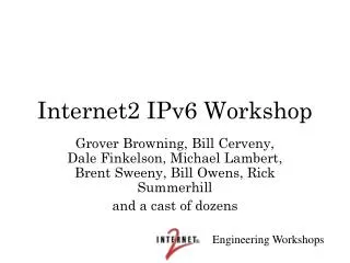
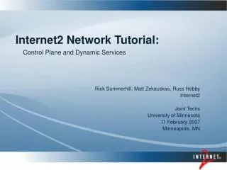
Control Plane and Dynamic Services Internet2 Network Tutorial: Rick Summerhill, Matt Zekauskas, Russ Hobby Internet2 Joint Techs University of Minnesota 11 February 2007 Minneapolis, MN
Collaborations with Other Networks High Level Overview: What are we trying to do? Review of Higher Level Objectives HOPI Testbed Overview Deployment on the Internet2 Network The DRAGON GMPLS Control Plane Control Plane Deployment
Working closely with Dante, Canarie, and ESnet on Inter-domain Interoperability Meetings in December and January, to continue in May Much ongoing work to utilize existing technologies Will meet in May after TERENA 2007 Also participating in the OGF working groups to insure standards compatibility For example, integrate existing topology disccovery efforts Collaboration with Other Networks
Support Applications that demand capabilities that are hard to support in a shared packet infrastructure Large bandwidth applications Applications that benefit from circuit characteristics, and that may be low bandwidth in nature Dynamically create data paths that look like circuits, often called ”lightpaths” Russ Hobby will talk more about this Networks taking different approaches: ESnet is taking an MPLS over Ethernet approach Internet2 (HOPI) taking an Ethernet VLAN approach Internet2 (Ciena) taking a SONET approach GEANT is taking a SONET approach Overview
Nodes located in 5 major cities on the Internet2 DWDM platform Dynamically create VLANS across the infrastructure Completely independent of the DWDM infrasturcture Likely to become more experimental as services are migrated to the Internet2 Network Discussions about a completely new approach at this meeting Overview of Control Plane Ideas: HOPI Testbed Overview
Team created to bring dynamic services to the Internet2 Network using the Ciena Platform Tom Lehman - lead Jerry Sobieski Xi Yang Chris Tracy Jarda Flidr Additional developer to be named later Develop services over the next two years incorporating the entire network Workshops in preparation, more later Development Team for DCS
Intra-domain Inter-domain Basic Ideas: Topology Path Computation Signaling Additional components Scheduling AAA Overview of Basic Control Plane Ideas
Service Request User Identification (certificate) Source Address Destination Address Bandwidth (50 Mbps increments) VLAN TAG (None | Any | Number) Schedule Dynamically Provisioned Dedicated Resource Path (“Circuit”) Domain Controller b 1 CSA 2 CSA can run on the client or in a separate machine (proxy mode) CSA a Client B Ethernet Mapped SONET or SONET Circuits Client A Internet2 DCS Client “Service” View
Service Request User Identification (certificate) Source Address Destination Address Bandwidth (50 Mbps increments) VLAN TAG (None | Any | Number) Schedule VLSR Domain Controller Switch Fabric 1 b 2 CSA CSA a Client B Client A Internet2 DCS Ethernet Mapped SONET or SONET Circuits Intra-Domain
Domain Controller Domain Controller Domain Controller CSA CSA RON Dynamic Infrastructure Ethernet VLAN RON Dynamic Infrastructure Ethernet VLAN Internet2 DCS Ethernet Mapped SONET Inter-Domain Inter-Domain
DRAGON Control Plane Status and Adaptation to Internet2 Network Slides by Tom Lehman University of Southern California Information Sciences Institute (USC ISI) And Others from the Development Team
Topics • DRAGON Control Plane Status • Thoughts/Considerations regarding Evolution to Internet2 Control Plane • Advanced Topics: Web Services, AAA, Scheduling • Next Steps and Timelines
DRAGON Control PlaneKey Components • Network Aware Resource Broker – NARB • Intradomain listener, Path Computation, Interdomain Routing • Virtual Label Swapping Router – VLSR • Open source protocols running on PC act as GMPLS network element (OSPF-TE, RSVP-TE) • Control PCs participate in protocol exchanges and provisions covered switch according to protocol events (PATH setup, PATH tear down, state query, etc) • Client System Agent – CSA • End system or client software for signaling into network (UNI or peer mode) • Application Specific Topology Builder – ASTB • User Interface and processing which build topologies on behalf of users • Topologies are a user specific configuration of multiple LSPs
Multi-Domain Control PlaneThe (near-term) big picture • Multi-Domain Provisioning • Interdomain ENNI (Web Service and OIF/GMPLS) • Multi-domain, multi-stage path computation process • AAA • Scheduling GEANT Internet2 Network RON RON Dynamic Ethernet Dynamic Ethernet TDM Domain Controller ESNet Ctrl Element Ethernet Data Plane SONET Switch Control Plane Adjacency IP Network (MPLS, L2VPN) LSP Router
CHI SEA NY CLPK GWU DC LA MCLN DCNE ARLG HOU DRAGON/HOPI Control Plane Provisioning Environment • GMPLS Multi-layer, Multi-Domain • Ethernet Service Provisioning • Dynamic dedicated VLAN based connections IGP-TE IGP-TE GMPLS Provisioned LSP Dedicated Ethernet VLAN “Circuit” UNI UNI Ethernet Layer Ethernet Layer Switched WDM Optical Layer Static Optical Layer HOPI Dynamic Ethernet Network DRAGON Multi-Layer GMPLS Network ENNI Domain Boundary
AS 2 AS 1 IP Control Plane AS 3 IP Control Plane IP Control Plane VLSR Router MPLS LSP Ethernet over SONET VLSR Ethernet over WDM End System Ethernet End System Ethernet Segment VLSR Established VLAN Lambda Switch SONET Switch Ethernet Segment VLSR Established VLAN Router Heterogeneous Network TechnologiesComplex End to End Paths “horizontal” multi-layer adaptations for multi-domain
DRAGON Control Plane Interoperation with Ciena Domain • Three Options • All have one NARB per Ciena Domain, receives topology information from Ciena Domain (ENNI, CORBA, static configuration ?) • GMPLS • One VLSR per Core Director; front end for signaling • Handles AAA, any special purpose configuration not handled by current GMPLS protocols (edge VLAN mapping adjustment for instance), other unique processing associated with peer entities • GMPLS Wrapper over Management Plane • One VLSR per Core Director Domain • Presents GMPLS to the outside world (probably as single opaque network with multiple external connections) • Use CORBA for Core Director Provisioning • GMPLS Wrapper over Management Plane (Option 2) • Same as above but use a “management style” system which talks to Ciena Domain via UNI or ENNI
Ongoing Ciena Testing • Resource Partitioning. Can resources be partitioned such that control plane (OSRP) provisioned resources and manually (management system) can be isolated from each other? We believe this is possible • Is it possible to police VLANS? Can each VLAN be policed and rate limited independently? We believe this is also possible! • Looking forward to UNI2.0 and ENNI availability • VCAT/LCAS interoperability with other vendors? • Will GFP encapsulated ethernet frames be interoperable with other vendors?
VLSR(Virtual Label Switching Router) • GMPLS Proxy • (OSPF-TE, RSVP-TE) • Local control channel • CLI,TL1, SNMP, others • Used primarily for ethernet switches XML Interface ASTB Web page CLI Interface One NARB per Domain • Provisioning requests via CLI, XML, or ASTB
VLSR(Virtual Label Switching Router) • RSVP Signaling module • Originated from Martin Karsten’s C++ KOM-RSVP • Extended to support RSVP-TE (RFC 3209) • Extended to support GMPLS (RFC 3473) • Extended to support Q-Bridge MIB (RFC 2674) • For manipulation of VLANs via SNMP (cross-connect) • Extended to support VLAN control through CLI • OSPF Routing module • Originated from GNU Zebra • Extended to support OSPF-TE (RFC 3630) • Extended to support GMPLS (RFC 4203) • Ethernet switches tested to date • Dell PowerConnect, Extreme, Intel, Raptor, Force10
NARBNetwork Aware Resource Broker • Interdomain Routing • hierarchical link state • Carries a modified TEDB that can support • AAA • Scheduling • Path Computation Element and ERO (loose and strict) generation InterDomain Exchange NARB NARB NARB End System End System AS 1 AS 3 AS 2
NARB(Network Aware Resource Broker) • NARB is an agent that represents a domain • Intra-domain Listener • Listens to OSPF-TE to acquire intra-domain topology • Builds an abstracted view of internal domain topology • Inter-domain routing • Peers with NARBs in adjacent domains • Exchanges (abstracted) topology information • Maintains an inter-domain link state database • Path Computation • Performs intra-domain (strict hop) TE path computation • Performs inter-domain (loose hop) TE path computation • Expands loose hop specified paths as requested by domain boundary (V)LSRs. • Hooks for incorporation of AAA and scheduling into path computation via a “3 Dimensional Resource Computation Engine (3D RCE)” • The Traffic Engineering DataBase (TEDB) and Constrained Shortest Path Computation (CSPF) are extended to include dimensions of GMPLS TE parameters, AAA constraints, and Scheduling constraints. • 3D RCE is the combination of 3D TEDB and 3D CSPF • http://dragon.east.isi.edu/data/dragon/documents/dragon-infocom-APBM-workshop-apr282006.pdf
What is the HOPI Service? • Physical Connection: • 1 or 10 Gigabit Ethernet • Circuit Service: • Point to Point Ethernet VLAN Circuit • Tagged or Untagged VLANs available • Bandwidth provisioning available in 100 Mbps increments • How do Clients Request? • Client must specify [VLAN ID|ANY ID|Untagged], SRC Address, DST Address, Bandwidth • Request mechanism options are GMPLS Peer Mode, GMPLS UNI Mode, Web Services, phone call, email • Application Specific Topology is a user specific instantiation of multiple individual circuits • What is the definition of a Client? • Anyone who connects to an ethernet port on an HOPI Force 10 Switch; could be RONS, GIgaPops, other wide area networks, end systems
Ethernet switch VLSR PC Ethernet switch Ethernet switch VLSR PC VLSR PC Ethernet switch Ethernet switch VLSR PC VLSR PC Ethernet switch VLSR PC GMPLS ProvisionedEthernet Services • Multiple Ethernet Provisioning Options • Point to Point Ethernet VLAN based LSPs • Ethernet switch (vendor specific) features applied to guarantee LSP bandwidth in increments of 100 Mbit/s • Edge connection flexibility provided by use of “Local ID” feature which allows flexible combinations of one port, multiple ports, tagged ports, and untagged ports to be glued on to end of LSP. Can be dynamically adjusted. • Users can request services via Peer to Peer GMPLS, UNI style GMPLS, or via an XML application interface • Ethernet VLAN space is “flat” across provisioned space. Constrained based path computation utilized to find available VLAN Tags. • VLAN tags treated in a similar manner to wavelengths “Local ID” for Egress Control User Requests: • Peer to Peer • UNI • XML API VLAN YY LSP VLAN XX LSP
Ethernet VLAN based Provisioning • Local ID defines the VLAN tag/edge port mapping • Several options; tagged, untagged, single port, port groups, automatic • Local ID definitions can be adjusted dynamically • OSPF • configure vlans on each interface • advertise out in IfSwCap Descriptor TLV inside a TE Link LSA • update vlans availability and bandwidth in response to provisioning • similar to the existing ifswcap-specific-psc and ifswcap-specific-tdm • RSVP ERO • proprietary Unnumbered Interface ID Subobjects (UnNumIfID) used to encode VLAN information in ERO • 32-bit UnNumbered Interface ID: type(1byte):value(24bits, vlan tag info) • NARB/RCE • listen to OSPF • path computation with bandwidth and vlan constraints • create EROs with UnNumIFID objects • Driven by need to provision across HOPI (10 gigabit interfaces)
DRAGON Provisioning Web Page Web Page Interface
Application Specific Topologies using XML C A B <topology> <resource> <resource_type> eVLBI.Mark5a </resource_type> <name> Haystack.muk1 </name> <ip_addr> muk1.haystack.mit.edu </ip_addr> <te_addr> muk1-ge0.haystack.mit.edu </te_addr> <appl> /usr/local/evlbi_script </appl> </resource> <resource> <resource_type> eVLBI.Mark5a </resource_type> <name> Westford1 </name> <ip_addr> wstf.haystack.mit.edu </ip_addr> <te_addr> wstf-ge0.haystack.mit.edu </te_addr> <appl> /usr/local/evlbi_script </appl> </resource> <resource> <resource_type> EtherPipeBasic </resource_type> <src> Haystack.muk1 </src> <dest> Westford.muk1 </dest> <datarate> 1 Gbs </datarate> </resource> </topology> A B C
Application Specific Topologies • Live demonstration at Internet2 Spring Member Meeting (April 2006, Washington DC) • See www.internet2.edu for webcast of “HOPI update” presentation. • Set up global multi-link topologies • ~30 seconds
Ethernet Layer Switched SONET Layer (vcat, lcas) Switched WDM Optical Layer Internet2 Network: Infrastructure with Multiple Services “ Routed IP Network” Router Layer Ethernet Layer Switched SONET Layer (vcat, lcas) “SONET Switched Network” Provisioned Topologies Switched WDM Optical Layer “Ethernet VLAN Switched Network (i.e., HOPI)” Separate (Peering) Control Plane Instantiations for each of the above Multi-Layer GMPLS Networks
Dynamic Circuit Service • Physical Connection: • 1 or 10 Gigabit Ethernet • OC-3, OC-12, OC-48, OC192 SONET • Circuit Service: • Point to Point Ethernet VLAN Circuit • Point to Point Ethernet Framed SONET Circuit • Point to Point SONET Circuit • Bandwidth provisioning available in 50 Mbps increments (STS-1 granularity) • How do Clients Request? • Client must specify [VLAN ID|ANY ID|Untagged], SRC Address, DST Address, Bandwidth • Request mechanism options are GMPLS Peer Mode, GMPLS UNI Mode, Web Services, phone call, email • Application Specific Topology is a user specific instantiation of multiple individual circuits • What is the definition of a Client? • A Device on the network requesting a circuit connection
Control Plane Objectives • Multi-Service, Multi-Domain, Multi-Layer, Multi-Vendor Provisioning • Basic capability is the provision of a “circuit” in above environment • In addition, need control plane features for: • AAA • Scheduling • Easy APIs which combine multiple individual control plane actions into an application specific configuration (i.e., application specific topologies)
Key Control Plane Features(for Connection Control) • Routing • distribution of "data" between networks. The data that needs to be distributed includes reachability information, resource usages, etc • Path computation • the processing of information received via routing data to determining how to provision an end-to-end path. This is typically a Constrained Shortest Path First (CSPF) type algorithm for the GMPLS control planes. Web services based exchanges might employ a modified version of this technique or something entirely different. • Signaling • the exchange of messages to instantiate specific provisioning requests based upon the above routing and path computation functions. This is typically a RVSP-TE exchange for the GMPLS control planes. Web services based exchanges might employ a modified version of this technique or something entirely different.
Key Control Plane Key Capabilities • Domain Summarization • Ability to generate abstract representations of your domain for making available to others • The type and amount of information (constraints) needed to be included in this abstraction requires discussion. • Ability to quickly update this representation based on provisioning actions and other changes • Multi-layer “Techniques” • Stitching: some network elements will need to map one layer into others, i.e., multi-layer adaptation • In this context the layers are: PSC, L2SC, TDM, LSC, FSC • Hierarchical techniques. Provision a circuit at one layer, then treat it as a resource at another layer. (i.e., Forward Adjacency concept) • Multi-Layer, Multi-Domain Path Computation Algorithms • Algorithms which allow processing on network graphs with multiple constraints • Coordination between per domain Path Computation Elements
Inter-Domain Topology Summarization Full Topology Semi-topo (edge nodes only) Maximum Summarization • User defined summarization level maintains privacy • Summarization impacts optimal path computation but allows the domain to choose (and reserve) an internal path
VLSR uni-subnet signaling flow uni uni data flow LSR upstream LSR downstream CD_z CD_a Ciena Subnet subnet signaling flow Integration Core Director Domain into the End-to-End Signaling • Signaling is performed in contiguous mode. • Single RSVP signaling session (main session) for end-to-end circuit. • Subnet path is created via a separate RSVP-UNI session (subnet session), similar to using SNMP/CLI to create VLAN on an Ethernet switch. • The simplest case: one VLSR covers the whole UNI subnet. • VLSR is both the source and destination UNI clients. • This VLSR is control-plane ‘home VLSR’ for both CD_a and CD_z. • UNI client is implemented as embedded module using KOM-RSVP API.
routed network Control PC (VLSR) Control PC (VLSR) Local Network Local Network Client System Client System Indianapolis Bloomington I2 DCS Development Lab
An Example of How to Connect to HOPI and the Internet2 Network - Phase 1 • Campus connects through RON using static VLANs and deploys VLSR on PC connected to switch (GMPLS control plane) • Ethernet based • Connect to HOPI control plane
Phase 2 • Add NARB (could be same PC) • Separates the campus domain from HOPI domain • Now have separate control planes
Phase 3 • When ready, RON implements GMPLS control plane
Phase 4 • Move to the Multiservice Switching Infrastructure on the Internet2 Network • There are many other possible alternatives
Workshops • Two day workshop • Provide a working knowledge of how to design and deploy a GMPLS based dynamic services network • Overview of GMPLS architecture • RSVP and OSPF protocols • Basic Control Plane Concepts • Routing, Path Computation, Signaling
Workshops, continued • Hands-on workshop, attendees will: • Implement a dynamic services test-bed (Ethernet based), using the DRAGON GMPLS Software Suite • Schedule: • First day will focus on concepts and basic control plane design and implementation • Second day will explore inter-domain dynamic services and provisioning • Target Audience: Senior Network Engineers familiar with current R&E network infrastructure, IP architectures, and ethernet switching. • See http://add this in