Download
1 / 38
430 likes | 1.09k Views
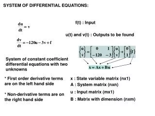
BUS2000 Busbar Differential Protection System. Differential overcurrent system with percentage restraint protection. Typical Busbar Arrangements. Single Busbar Double Busbar with Coupler Breaker and a Half Double Breaker Double Busbar with Transfer Bar Segregated Busbars with Coupler.

E N D
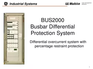
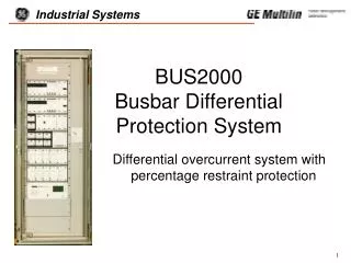
BUS2000 Busbar Differential Protection System Differential overcurrent system with percentage restraint protection
Typical Busbar Arrangements • Single Busbar • Double Busbar with Coupler • Breaker and a Half • Double Breaker • Double Busbar with Transfer Bar • Segregated Busbars with Coupler
Types of Protection Schemes • Low Impedance • High Impedance • Medium Values • High Values
Saturation of the Auxiliary CTs • A. Primary Fault Current • B. Secondary Current from the Source CTs • C. Secondary Current in the Faulty CT • D. Differential Current
Low Impedance Protection Current Detection + Second Criteria • Time-delayed Overcurrent Relays • Directional Overcurrent Relays • Restraint Overcurrent relays • CT Saturation Detectors
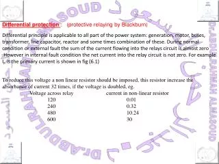
High Impedance Protection • WHERE: • RL= CONNECTION WIRES RESISTANCE • IF = SECONDARY RMS CURRENT VALUE IN TI3 • VR = DIFFERENTIAL RELAY VOLTAGE • VS = CT MINIMUM SATURATION VOLTAGE • VOP = OPERATION VOLTAGE • VR = IF x (2RL + RS) • VOP > VR Stability Criteria • VS > VOP Operation Criteria • TI3 Totally Saturated • RS CT Secondary Winding R Value
Differential Overcurrent Relay with Percentage Restraint & Stabilizing Resistor
BUS2000-Auxiliary CT. Magnetizing Curve of the Secondary Side
Numerical Monitoring Module • Differential and Restraint Currents Metering Information • Full Human-Machine Interface (Keypad + Graphic Display) • IRIG-B Time Synchronization • Alarm Treatment • Differential Protection Outputs Status
Numerical Monitoring Module (cont) • Oscillography Waveform Capture • Event Record • RS232 or fiber optics Communications • Configurable I/O • Undervoltage Supervision
BUS2000-Overcurrent and Breaker Failure (5 feeders) Protection
External Connections Diagram of Single Busbar BUS2000 System
BUS2000-Settings • K for Sensitivity • K and RE as low as possible • RE for CT requirements for Overvoltage Conditions
Key Advantages • Flexibility • Independent setttings for K and RE done in the field without any additional changes • Wide Setting Range • Suitable for all kinds of installations • Measurement Units Supervision • Current Circuits Supervision
Key Advantages (cont’d) • Single-Three Phase Breaker Failure • Test Rack Independent from the protection • Easy Commisioning (accesible terminal blocks) • Suitable for updating of old Substations • Operating Principles well proven in the field • Numerical Monitoring Module