DC Generator
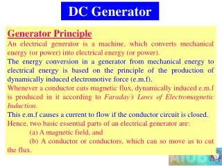
DC Generator. The dc machine operating as a generator is driven by a prime mover at a constant speed and the armature terminals are connected to a load. In many applications of dc generators, knowledge of the variation of the terminal voltage with load current is essential.

DC Generator
E N D
Presentation Transcript
DC Generator • The dc machine operating as a generator is driven by a prime mover at a constant speed and the armature terminals are connected to a load. • In many applications of dc generators, knowledge of the variation of the terminal voltage with load current is essential.
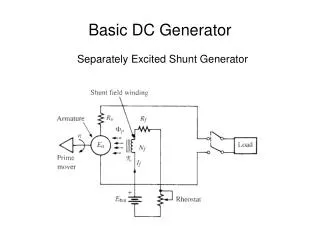
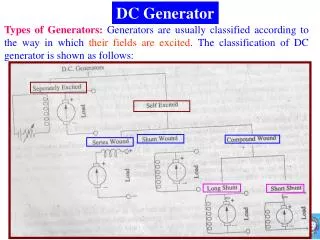
Separately Excited DC Generator • The field winding is connected to a separate source of dc power, i.e. another dc generator, a controlled rectifier, a diode rectifier, or a battery. • The steady-state defining equations are External Characteristic
Separately Excited DC Generator Vt = Ea – ( IaRa +VAR) Load charac. Vt =It.RL • The terminal and load characteristic is shown in the Fig. • The point of intersection between the generator external characteristic and the load characteristic determines the operating point, that is, the operating values of the terminal voltage Vt and the terminal current It
Armature Reaction • With no current flowing in the armature, flux in the machine is established by the mmf produced by the field current (a). • However, if the current flows in the armature circuit it produces its own mmf (hence flux) acting along the q axis (b). Hence the original flux from field is disturbed. • Saturation (flux density under one pole increased-> reduction flux per pole oppose aid
Armature Reaction Flux density ‘dip’ due to large magnetic reluctance • Developed diagram • Armature Mmf (Fa) and flux density (Ba) • Flux density distribution Generated voltage- effect of armature reaction Flux ‘dip’ due to saturation near pole tip
Zero flux density region moves as armature current flows – cause poor commutation and sparking Distribution of air gap flux in multi polar machines
Armature Reaction At no load, Ia=0, Ea high, Ea = Vt Loaded, Ea drop due AR’ Ea = Vt + IaRa
Armature Reaction – Compensating Winding • The armature mmf distorts the flux density distribution and also produces the demagnetizing effect known as armature reaction. • Much of the rotor mmf can be neutralized by using a compensating winding, which is fitted in slots cut on the main pole faces. • These pole face windings are so arranged that the mmf produced by currents flowing in these windings are proportional of armature mmf but opposes the armature mmf.
Remedies for field distortion • By increasing the length of air gap – make reluctance high and strong mmf requires to force flux in air gap. • By providing machine with a compensating winding – produce mmf to neutralise mmf armature • By using interpole – small auxiliary pole • By reducing cross-section of pole pieces
Example 5 Q. A 12 kW, 100 V, 1000 rpm dc shunt generator has armature resistance Ra= 0.2 ohm, shunt field winding resistance Rfw= 80 ohm, and Nf= 1200 turns per pole. The rated field current is 1.0 ampere. The magnetization characteristic at 1000 rpm is shown in the next figure. The machine is operated as a separately excited dc generator at 1000 rpm with rated field current. • Neglect the armature reaction effect. Determine the terminal voltage, Vt, at full load (rated load). • Consider that armature reaction at full load is equivalent to 0.06 field amperes. (i) Determine the full load terminal voltage. (ii) Determine the field current required to make the terminal voltage Vt = 100 V at full-load condition. Sen pg. 151 Sol_pg10
Shunt (Self-Excited) Generator • In the shunt or self-excited generator the field is connected across the armature so that the armature voltage can supply the field current (5% of Ia rated). • Under certain conditions, this generator will build up a desired terminal voltage. • The circuit for the shunt generator under no-load conditions is shown below. Rf= Rfc + Rfw
Shunt Generator • If the machine is to operate as a self-excited generator, some residual magnetism must exist in the magnetic circuit of the generator. • Magnetization curve of the dc machine (Fig) • Also shown the field resistance line, which is a plot of RfIf versus If • A simplistic explanation of the voltage buildup process in the self-excited dc generator. • Assume field initially disconnected and armature is driven at certain speed. Small voltage Ear appears due to the residual flux. • Then switch closed. If flows in the field . If this if add to previous flux, then if increase. This increase Ear to Ea1 then it will build up. Ef=IfRf Assume no field current, Ear due to residual flux
Shunt Generator • Voltage buildup in the self excited dc generator for various field circuit resistances (Fig) • At some resistance value Rf3, the resistance line is almost coincident with the linear portion of the magnetization curve, is known as the critical field circuit resistance., Rf3 = Ef3/if3 • If the resistance is smaller than this value, such as Rf1 or Rf2, the generator will buildup higher voltages. Three conditions for voltage build up: • Residual magnetism must be present. • Field winding mmf aids residual magnetism. • Rf < Rfc Rf1<Rf2<Rf3
Example 6 • The dc machine in Example 5 is operated as a self-excited (shunt) generator at no load. • Determine the maximum value of the generated voltage. • Determine the value of the field circuit control resistance (Rfc) required to generate rated terminal voltage. • Determine the value of the critical field circuit resistance. Sol_pg15 Sen pg. 154
Step --Maximum Ea at min Rf, i.e .Rf = Rfw = 80 0hm– Draw line 80if --- Ea = 111 V • ii. At rated, Ia = 12k/100= 120 A. ; Vt= 111-120(0.1) = 100V Rf = 80 ohm 111 V
Shunt Generator – Voltage (Vt)–Current (Ia) Characteristics/ External Characteristic Vertical line represent volt drop, IaRa Magnetising curve V-I curve
Voltage – Current Characteristics Terminal voltage drop if armature reaction take into account . i.e Vta < Vt1. Slide down the triangular pqr, until it suites one complete area under OCC and field line, op., then find Vta. Ra IfAR Ifeff = If (actual) - qr Vt1 – No armature reaction Vta – with armature reaction qr =bc
Example 7 • The dc machine in Example 5 is operated as a self-excited (shunt) generator. • The no load terminal voltage is adjusted to 100V. Determine the full load terminal voltage. Neglect armature reaction. • Repeat (a), assuming that the effect of armature reaction at full load is equivalent to 0.06 A field ampere, that is If(AR) = 0.06 A. • Determine the maximum value of the armature current and corresponding value of the terminal voltage. Assume If(AR) proportional to Ia. • Determine the generator short-circuit current. Sen pg. 159
Example 8 The following is the magnetic characteristic of a DC generator shunt connected driven at 1000 rpm. Ea (V) 160 260 390 472 522 550 If (A) 1 2 4 6 8 10 Determine: i. The voltage to which it will excite on open circuit ii. The approximate value of the critical resistance of the shunt circuit iii. The terminal potential different (terminal voltage) and load current for a load resistance RL of 4 . The armature and field resistances are 0.4 and 60 respectively. Solution : i).Draw OCC and draw field load line, - 540 V ii.) Draw tangential line to OCC, 160 ohm. iii.) Need to draw external characteristics ( VT Vs IL), then draw RL.IL line find data VT & IL) at cross over Sol_Emxple 8
Solution. Ea (V) 160 260 390 472 522 550 If (A) 1 2 4 6 8 10 Term. Voltage Vt 60 120 240 360 480 600 Vt = 60 x If IaRa = Ea-Vt 100 140 150 112 42 … Armature Ia =IaRa/0.4 250 350 375 280 105 Load current IL= Ia – If 249 348 371 274 94 Then plot load line ILx4 --- Answ : Vt = 470, Ia= 112.5
Compound DC Machines To overcome the IaRa drop and decrease of pole flux due to armature reaction, the additional winding (series winding) is mounted on the field poles along with shunt winding. It provides additional mmf to increase or decrease pole flux.
Compound DC Machines for both connection Constant current – useful as a welding generator • sh – flux/per pole in shunt field winding • sr – flux/per pole in series field winding • Commulative compound machine – flux aid each other • Differential compound machine – flux oppose each other V-I characteristics of compound DC generators
Example 9 • The dc machine in Example 5 is provided with a series winding so that it can operate as a compound dc machine. The machine is required to provide a terminal voltage of 100 V at no load as well as at full load. (i.e. zero voltage regulation) by cumulatively compounding the generator. If the shunt field winding has 1200 turns per pole, how many series turns per pole are required to obtain zero voltage regulation. Assume a short-shunt connection and that the series winding has a resistance Rsr = 0.01 ohm. PC Sen pg 163 Sol_pg24
Series Generator Field winding provides flux as the armature current flows through it. A load RL must be connected Graf :Magnetization curve, (Ea vs. Ia ) and Ia(Ra+Rsr) vs. Ia Vt’- effect of armature reaction Terminal characteristic (Vt Vs. Ia) can be plotted at varios Ia . Data Vt obtained from magnetising curve.
V-I Characteristics V-I characteristics of DC generators
Example 10 Given Ra = 0.25 ohm Sol. Q2 2007/08-2
Example: 2008/09 The following figures give the open circuit characteristics of a dc shunt generator at 300 rpm. The field resistance of the machine is adjusted to 354.5 and the speed is 300 rpm. The voltage drop across the armature resistance, IaRa is 12 volts. i. Determine graphically the no-load voltage ii. Determine the full load voltage. Neglect armature reaction effects iii. Repeat (ii), assuming that the effect of armature reaction at full load is equivalent to 0.05 field amperes iv. Determine the critical resistance v. Determine the critical speed for the given field resistance vi. What additional resistance must be inserted in the field circuit to reduce the load voltage to 175 V. Sol_pg28