Download
1 / 66
660 likes | 788 Views
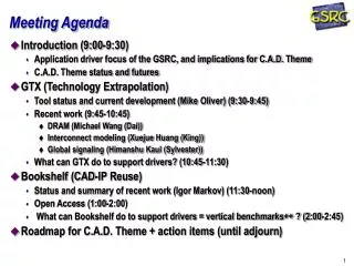
Meeting Agenda. Progress Some Issues SC. Motion Mechanism HX Cell. Target. Progress. “Pre-Preliminary” Design Document Nice work by Dave Meekins Fan (25 l/s) Design sidetracked for HX work But new motor here, impellers, etc. ANSIS fluid flow software bought

E N D
Progress Some Issues SC Motion Mechanism HX Cell Target
Progress • “Pre-Preliminary” Design Document • Nice work by Dave Meekins • Fan (25 l/s) • Design sidetracked for HX work • But new motor here, impellers, etc. • ANSIS fluid flow software bought • HX (2500+ W: 4K HX AND15K HX) • Detailed design + drawings basically finished • Review in progress- very positive feedback • Dave has done a great job on this- very impressive • Motion Mechanism • Conceptual design reportby Jim Dunne • Scattering Chamber • Bates/Sample SC at JLab now. Needs to be stretched. • Cell & manifold will be outsourced
Some Issues • Tgt is a FY06 spending priority. But: • Tgt grp getting busier • Pol tgt in Hall B (& Hall C) • GEp Hall C requires new SC & complete redesign of loop • As our schedule stretches, we lose priority • Need collab. Input on dummy tgts
Scattering Chamber • Bates/Sample SC here now • Thanks to our collaborators at Bates • Msrs ~ 3’ x 3’ x 5’ tall • Will need to make it taller for our loop • But 3’x3’ footprint OK • Stndrd Hall C SC changes may help us to stretch (GEp needs a new one) • New service connections, etc. for sure
Sample Tgt: Δρ/ρ < 1000 ppm • Specs: • 25 l H2 inventory • Vvol=7.9 l/s @ 30 Hz • Expected ΔT=0.3K @ 1kW • 40 cm, 40 μA (~500 W) • Outer cell 7 cm φ, • 0.38mm thick • Windsock tapers to 3 cm φ, • 0.13 mm thick • Reynolds # ~ 107 • m = 550 g/s @ 30 Hz • Vs=5 m/s @ 30 Hz • 3mm φ raster • External pump .
In Beamline New lifter section Existing Sample SC
Motion Mechanism • Conceptual design report by Jim Dunne • sabbatical next year to build lifter! • Recycles parts from standard pivot tgt • BDS5 motor, driver, control software • Motion in x (~±3 cm)& y (~30 cm) • Long thin SS 8” Φ pipe to isolate loop • Flexlines • 3-axis lifter, single motor ala Hall C
3 Targets (& an out) Geometry LH2 Al Dummy X0 ~ LH2 X0 Full Current C X0 ~ LH2 X0 Target OUT position
VPI Sim:Weighted θ & Φ accepted at FPD.3.5 mil cell window.10 mil vacuum window.
½” fin tube 14 fpi 3 loops in series, Each at inner, mid, & outer Layers to equalize ΔP 4K HX >2 kW 3 atm 1.2 atm 4K 20K 3” Φ
Leak test: 500 psi !
15K HX >1 kW 15 atm 1.2 atm 14K 20K 15K HX design similar to 4K HX
Cell Design • Thickness of cell & windsock a compromise between engineering & experimental needs. • Present plan: thin walled cylindrical Al cell with exit window thin nipple. • Entrance window Be, no He backing cell. • Flow diverter/windsock a conical, axially symmetric longitudinal Al tube. • Total thickness of these components must be modeled. Special fluid ANSIS just bought. • All joints in the cell/cell block will be welded or mechanical (no soldering)
VPI Sim. of transverse cell thickness 10 mils ~ OK (ΔR~2%) Mechanism for loss of rate seems to be Bremsstrahlung ΔE, leading to greater Δθ in QTOR Be cell Al cell Transverse cell thickness in mils
cell block outie innie 10 mil Al Perforated windsock nipple
Beam Power Pb(W) = Ib(μA) · (g/cm3) ·t(cm) · dE/dx(MeV/g/cm2) ~ 2100 W • Need additional power for: • PID control • Conductive losses • QW goal:2500 W With: 180 μA, 0.072 g/cm3, 35 cm, 4.7 MeV/g/cm2
Under uniform pressure p, the following stresses exist longitudinal tangential
Exotic materials • Try Be or an AlBe alloy. • Ultimate strength is about ½ that of Al 7075 • Radiation length is 4 times larger • There is some gain in doing this. • Many issues with this choice • Safety • Machinability Something thin enough to be useful may not be practicable.
Current Status • Design of Hx’s complete • Drafts to be approved by Cryo • Assembly can begin in house at this point • Cell design is underway plan to have this finished by June 1 • Loop layout complete by June 1 • Pump prelim design complete by July 1 • Pump tests in Sept • Safety (relief sizing gas handling …)
Squeezing it dry If we’re close, how to get the last little bit? • Supplement with (more) 15K from ESR • Run target at 21K or 22K instead of 19K • Shave Preserve (350W 150W?) • Schedule during Hall A reconfig. (gain 5 g/s) • Run longer at lower beam current • Run at higher P higher T greater cooling power
Up/θ Horizontal Φ VPI Simulation: X & Y at the exit window of the tgt cell for events that hit the upper FPD. No mult. scat. in tgt.
Qweak Cooling Specs • 180 µA (parity quality) beam • 1.165 GeV in 1 pass (5.5 GeV 5 pass equiv.) • 35 cm LH2 target • 19K or 20K operating (return) temp. • ~2.5 kW cooling power required • ~2.1 kW beam power • ~0.4 kW overhead • Exceeds standard capacity of ESR (1.2 kW) • Experiment installation late 2007, 1st run ~ 6 mo.
Qweak/Cryo/Target Group Mtg Agreement on all fronts! • All parties now agree on load required: • (25 g/s 4K supply, 19K return) • All parties now agree on dual tgt design: • Up to 2500 W 4K HX • Up to 800 W 15K HX • All parties now agree dual HX concept works • Assumes current loads • Load balancing. Flexibility.
Conditions • Tgt return temp > 19K • Additional FEL load beyond present 20 g/s would create a conflict • Hall C HMS 80K • Hall C Moller on cold return • Hall A modest program (no high power tgt) • Special filling or extra/unusual demands reduce load temporarily on Qweak target
Happex Lessons • June ’04: Ran successfully off main CHL coldbox excess capacity. • Max flow received was 24 g/s • Max flow data acquired at was 20.4 g/s • Route: CHL-ESR-”15K supply”-20K return-ESR • actual supply temp. was ~4K, returned “warm” • Acc: 0.99 GeV/pass, 3.036 in Hall A. Hall B (4 GeV), Hall C off. Hall A spectrometers & septa on. • 19K LH2 results: 62-75 W/(g/s) cooling power • only actually pulled 6-8 g/s due to septa limitations • We need ~2100 W cooling power 28 g/s • 6.6K He target: estimated 23.7 W/(g/s) Fact: Hall A ran 24 g/s off CHL excess 4K capacity in summer 04!
Happex He: 6/10-16Happex H2: 6/19-7/25Hall C: on after 6/19 23 g/s
Outstanding Cryo Issues • Can Moller operate at 5K? • Using data for NiTi superconductors suggests yes • A test of 5K 3Tesla Moller operation should be performed • Moller would use ~3-4 g/s to increase total CHL draw to 19 g/s • Hall A lead flow still 1-2 g/s, total would be ~21 g/s • Scheme uses existing plumbing and refrigerators • Operational procedures for Target cool down/warm up, ESR trip/recovery, CHL trip/recovery would have to be adjusted. • Conditions would be similar to HAPEX 2004 running in Hall A
With 15K refrigerant Using modest flow of 15 g/s at the target 525 W of cooling power Dual Hx Possibilities • With 4K refrigerant • Using a modest flow of 15 g/s at the target • 1560 W of cooling power Total is ~2100 W of cooling power
Heat Exchangers • To make use of all refrigeration options • Use 2 Hx • 5K refrigerant High Power Hx • 15K refrigerant Auxiliary Hx • 4K Hx is large enough to provide > 3kW of power • 15K Hx is large enough to provide > 700W of power
5 Scenarios • CHL, QW 2 pass (>100% QW needs): • No cryo-load problems, but E/pass unpopular • CHL, QW 1 pass (80% QW needs): • Schedule during moderate Hall A load • Same solution Hall A Happex II is using summer ‘03 • Schedule while Hall A off (reconfig) 100% QW needs • Backup CHL (SBR) as is (60% QW): • Inefficient, insufficient • Upgraded SBR: • New xfer line, compressor, spare parts (~$1M) • Broader solution for JLab • 1.8 kW @ 4K (~75%), higher at 15K (being studied) • ESR Upgrade (>100% QW) • 4 kW goal, no load problems or QW limitations, broader sol’n. for JLab. $3M + 3 years. 1/03
Possible Sources of Cooling fragile! ESR 15K • supply: 15K @ 12 atm • return: 20K @ 3 atm • ΔH = 35 J/g • Need ~ 70 g/s • mmax~ 25 g/s • ESR 4K • supply: 4K @ 3 atm • return: 5.5K @ 1.2 atm • ΔH = 26 J/g • Need ~100g/s • mmax~ 50 g/s • CHL 4K • supply: 5K @ 3 atm • return: 20K @ 1.5 atm • ΔH = 104 J/g • Need ~ 24 g/s • mmax~ 20 g/s • (@ 5.5 GeV) ESR is 1200 W max, only half what we need close to what we need- in fact Happex got 24 g/s
CHL 4K Capacity • Minimum 190 g/s, Maximum 240 g/s • Depends on E/pass (5) • Flatout (~5.8 GeV): uses 215 g/s (for accelerator) • Need 5g/s for Hall A lead flow, + 5g/s reserve • Leaves only 15 g/s available for QW (60%) • Normal (< 5.5 GeV): uses 210 g/s • Still need ~ 10 g/s for lead flow + reserve • Leaves 20 g/s available for QW (80%) • Happex II solution, summer 04 • If scheduled during Hall A reconfig gain 5g/s QW (100%) • Reduced (< 3 or 4 GeV): uses 190-200 g/s • At least 30 g/s available for QW (>100%) 1/03
Refrigeration • There are 2 refrigerators possibly available for our use. • Standard ESR at 15K (~800W) • CHL extra capacity (~5-2500W) • Availability of this capacity is in question • Current FEL plans present Qweak with difficulties • We need upwards of 2500W for our target.
Squeezing out the Cooling Power • Run at higher P • 24 psia 40 psia • Run 2K subcooled • instead of 3K • Increase ballast volume to reduce pressure rise on boil • Win 3K ! 4K coolant win ~15% 15K coolant win 75%