Download
1 / 26
260 likes | 426 Views
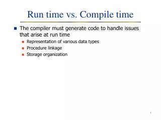
Topic 3: Run-Time Environment. Memory Model Activation Record Call Convention Storage Allocation Runtime Stack and Heap Garbage Collection. ABET Outcome.

E N D
Topic 3: Run-Time Environment Memory Model Activation Record Call Convention Storage Allocation Runtime Stack and Heap Garbage Collection
ABET Outcome • Understand the software conventions necessary to support various source languages, including data representation, storage allocation for the various storage classes of variables, visibility rules, call sequence, entry, exit, and return. • Ability to apply the knowledge of run time support system to trace the program execution. \course\cpeg421-08s\Topic-3.ppt
Slides Dragon book: chapter 7 Muchnick’s book: Chapter 5 Other readings as assigned in class or homeworks Reading List \course\cpeg421-08s\Topic-3.ppt
The execution environment provided by the system software services. The runtime environment dictates how executable code is loaded into memory, where data is stored, and how routines call other routines and system software routines. What Does Runtime Environment Do \course\cpeg421-08s\Topic-3.ppt
¤Issues • Software conventions, such as data layout and allocation • Mechanism to access variables • Procedure calling • Interface to OS, libraries, I/O devices, etc. ¤Names versus data objects Same name can refer to different data objects during execution; the runtime environment provides the mapping ¤Procedure activations • Each time a procedure is called, a new activation of that procedure occurs within an environment (who call it? where it was called from? What declarations are active at call site?) • Recursion: a new activation of same procedure can start before an early activation has ended Jobs of Runtime Environment \course\cpeg421-08s\Topic-3.ppt
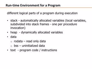
• Architecture -- Instruction Set Architecture (ISA) -- Data Types -- Register Usage Convention -- Memory System -- Addressing Model (the organization of data in registers and memory) • Operating system -- Memory organization and management -- Stack Usage Convention -- Special Register Initialization • Compiler -- Data layout -- Activation Record -- Calling convention Runtime Environment \course\cpeg421-08s\Topic-3.ppt
Memory Model Memory Layout Register usage Procedure calling convention Runtime Stack and Heap Related Topics \course\cpeg421-08s\Topic-3.ppt
MIPS Architecture Overview • Processor Features Full 32-bit operation, efficient pipelining, on-chip TLB (Translation Lookaside Buffer) for virtual-to-physical memory mapping, cache control, coprocessor interface • Registers 32 general 32-bit registers, a 32-bit Program Counter • ISA (Instruction Set Architecture) Each instruction is 32 bits long, three instruction formats (intermediate I-type, jump J-type and register R-type) • Memory Management System Physical memory addressing range of 4 Gbytes (32 bits). The virtual address space is divided into 2 Gbytes for users and 2 Gbytes for the kernel. • Addressing Model Defines a 64-bit doubleword, a 32-bit word, a 16-bit halfword and an 8-bit byte. Byte addressing. The byte ordering can be configured in either Big-endian or Little-endian format. \course\cpeg421-08s\Topic-3.ppt
MIPS Register Usage Convention \course\cpeg421-08s\Topic-3.ppt
Modern computer systems nearly always use virtual memory. The purpose of virtual memory is to make it appear as if a program has the full address space available. So the programming model has the full address space. User memory space (Virtual memory) OS memory space (Physical memory) Memory Model \course\cpeg421-08s\Topic-3.ppt
Why Virtual Memory • Why Virtual Memory • Limited physical memory size • 64MB to 2GB • Unlimited virtual memory size • Each process may have 4GB • Many processes in the system \course\cpeg421-08s\Topic-3.ppt
Virtual Memory/Physical Memory - Physical memory and virtual memory broke into fixed size pages; - Each physical page holds a virtual page (may come from different processes) - Only the active pages of each process reside in physical memory, physical memory works as cache of virtual memory (disk) - Other pages stay on disk \course\cpeg421-08s\Topic-3.ppt
Mapping Virtual Memory to Physical Memory Physical Memory Process 1 VM Process 2 VM OS U1/P0 U2/P0 Page 0 OS U1/P1 U2/P1 Page 1 U1/P0 U1/P2 U2/P2 Page 2 U2/P3 U1/P3 U2/P3 Page 3 U1/P3 U1/P4 U2/P4 Page 4 U1/P7 U1/P5 U2/P5 Page 5 U1/P6 U1/P6 U2/P6 Page 6 U2/P1 U1/P7 U2/P7 Page 7 On Disk \course\cpeg421-08s\Topic-3.ppt
Virtual Memory Layout Virtual address High Reserved for kernel Stack Stack segment Heap BSS Dynamic data Data segment Global Data Static data Data Text segment Text Reserved Low VM Layout – (User View) VM Layout – (OS View) \course\cpeg421-08s\Topic-3.ppt
Procedure Activation A procedure is activated when it is called. \course\cpeg421-08s\Topic-3.ppt
Activation Lifetime • Lifetime of an activation of procedure P is the sequence between first and last steps in execution of procedure body, including time spend executing any procedures called from P. • Structure program languages allow only nested procedure lifetimes • -- Allows use of stack to define runtime environment • -- Can show relations in procedure activation tree \course\cpeg421-08s\Topic-3.ppt
Activation Tree A data structure that represents the activations during the running of an entire program. Assumption Each execution of a procedure starts at the beginning of the procedure body and eventually returns control to the point immediately following the place where the procedure was called. \course\cpeg421-08s\Topic-3.ppt
Activation Tree (Con’t) • Features of activation tree • Each node is a procedure activation, each edge represents opening an activation while the parent activation is still open. The root node is the main program activation. • Flow of control in procedure calls corresponds to a preorder (depth-first) traversal of the activation tree. • Flow of control in procedure returns corresponds to a postorder traversal of the activation tree. • A node A is to the left of node B in the tree means the lifetime of A occurs before the lifetime of B. • We can use a control stack to keep track of live procedure activations. \course\cpeg421-08s\Topic-3.ppt
main fact(5) fib(4) fact(4) fib(3) fact(3) fib(2) fib(1) fact(2) fact(1) Activation Tree: Example fact(x) {… fact(x-1);} fib(y) {int i; … fib(y-1)+fib(y-2);} main() {fact(5); fib(4);} fib(2) \course\cpeg421-08s\Topic-3.ppt
Activation Record • A data structure containing the variables belonging to one particular scope (e.g. a procedure body), as well as links to other activation records. • Activation records are usually created (on the stack) on entry to a procedure and destroyed on exit. \course\cpeg421-08s\Topic-3.ppt
Contents in Activation Record • Static link to encompassing scope • Local variables • Return address to branch to caller’s code • Temporaries • Saved register contents • Storage for outgoing arguments • Stored in fixed order in frame. Frame pointer points to frame beginning. Fields are referenced using offset The sizes of almost all the contents can be determined at compiler time –except for dynamic arrays or other variable length data objects \course\cpeg421-08s\Topic-3.ppt
Activation Record Layout Layout form dragon book \course\cpeg421-08s\Topic-3.ppt
Frame pointer and stack pointer •When a procedure starts running, the frame pointer and the stack pointer contain the same address. • While the procedure is active, the frame pointer, points at the top of the stack (the last word that was pushed onto the stack, the top of the stack.) • The stack pointer may be changed its value while a procedure is active but the frame pointer does not change its value while a procedure is active. The variables will always be the same distance from the unchanging frame pointer. \course\cpeg421-08s\Topic-3.ppt
Activation Record Layout (Con’t) high addr. previous frame Incoming arguments (frame pointer) fp frame offset Current frame Outgoing arguments low addr. (stack pointer) sp \course\cpeg421-08s\Topic-3.ppt
Stack of Activation Records fact(x) {… fact(x-1);} fib(y) {int i; … fib(y-1)+fib(y-2);} main() {fact(5); fib(4);} From OS Top of stack main From main Top of stack y main fib(4) i fact(5) fib(4) From fib(4) y Top of stack fact(4) fib(3) fib(2) fib(3) i fact(3) fib(2) fib(1) From fib(3) y Top of stack fact(2) fib(1) i fact(1) \course\cpeg421-08s\Topic-3.ppt
Stack of Activation Records fact(x) {… fact(x-1);} fib(y) {int i; … fib(y-1)+fib(y-2);} main() {fact(5); fib(4);} Back to OS main Top of stack y main fib(4) i fact(5) fib(4) Back to main Top of stack Top of stack y y fact(4) fib(3) fib(2) fib(2) fib(3) i i Back to fib(4) fact(3) fib(2) fib(1) Top of stack Top of stack y fact(2) fib(1) i Back to fib(3) fact(1) \course\cpeg421-08s\Topic-3.ppt Top of stack fib(1)