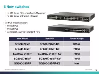
Module 5 - Switches
220 likes | 328 Views
This module covers key aspects of Local Area Network (LAN) design, detailing the four major goals: functionality, scalability, adaptability, and manageability. It outlines systematic LAN design steps, comparing Layer 1, 2, and 3 structures. The three-layer design model is discussed, highlighting the functions of access, distribution, and core layers. The module also lists various Cisco switch features for each layer and offers insights into server placement, segmentation, and broadcast domain management to optimize network performance and reliability.

Module 5 - Switches
E N D
Presentation Transcript
Module 5 - Switches CCNA 3 version 3.0
Overview • Describe the four major goals of LAN design • List the key considerations in LAN design • Understand the steps in systematic LAN design • Understand the design issues associated with the Layer 1, 2, and 3 LAN structure, or topology • Describe the three-layer design model • Identify the functions of each layer of the three-layer model • List Cisco access layer switches and their features • List Cisco distribution layer switches and their features • List Cisco core layer switches and their features
LAN Design Goals • Functionality – The network must work. The network must allow users to meet their job requirements. The network must provide user-to-user and user-to-application connectivity with reasonable speed and reliability. • Scalability – The network must be able to grow. The initial design should grow without any major changes to the overall design. • Adaptability – The network must be designed with a vision toward future technologies. The network should include no element that would limit implementation of new technologies as they become available. • Manageability – The network should be designed to facilitate network monitoring and management to ensure ongoing stability of operation.
LAN design considerations MDF/IDF To maximize available LAN bandwidth and performance: • The function and placement of servers • Collision detection issues • Segmentation issues • Broadcast domain issues Note: This graphic is confused with its location of the MDF and IDF. Not sure what it is trying to show. IDF
LAN design considerations • Servers can be categorized into two distinct classes: • Enterprise servers • Workgroup servers • An enterprise server supports all the users on the network by offering services, such as e-mail or Domain Name System (DNS) that everyone in an organization would need because it is a centralized function. • A workgroup server supports a specific set of users, offering services such as word processing and file sharing. • Other examples might include applications that are specific to a group of users. Server Placement
LAN design considerations • Enterprise servers should be placed in the main distribution facility (MDF). • Traffic to the enterprise servers travels only to the MDF and is not transmitted across other networks. (Not necessarily. If you have a “routed core” it will travel across other networks.) Server Placement
LAN design considerations • Ideally, workgroup servers should be placed in the intermediate distribution facilities (IDFs) closest to the users accessing the applications on these servers. • By placing workgroup servers close to the users, traffic only has to travel the network infrastructure to an IDF, and does not affect other users on that network segment. • Layer 2 LAN switches located in the MDF and IDFs should have 100 Mbps or more allocated to these servers. Server Placement
LAN design considerations • Segmentation is the process of splitting a single collision domain into smaller collision domains. • Creating smaller collision domains reduces the number of collisions on a LAN segment, and allows for greater utilization of bandwidth. • Layer 2 devices such as bridges and switches can be used to segment a LAN into smaller collision domains. • A broadcast domain refers to the set of devices that receive a broadcast data frame originating from any device within that set. • Processing the broadcast data will consume the resources and available bandwidth of the host. • Layer 2 devices such as bridges and switches reduce the size of a collision domain but do not reduce the size of the broadcast domain. • Routers reduce the size of the collision domain and the size of the broadcast domain at Layer 3.
LAN design methodology • Gather requirements and expectations • Analyze requirements and data • Design the Layer 1, 2, and 3 LAN structure, or topology • Document the logical and physical network implementation 2 1 3 4 OSI layer topology map LAN logical map LAN physical map Cut sheets VLAN logical map Layer 3 logical map Addressing maps
Layer 1 design • One of the most important components to consider when designing a network is the physical cabling. • Design issues at Layer 1 include the type of cabling to be used, typically copper or fiber-optic, and the overall structure of the cabling.
Layer 1 design • In a simple star topology with only one wiring closet, the MDF includes one or more horizontal cross-connect (HCC) patch panels. • HCC patch cables are used to connect the Layer 1 horizontal cabling with the Layer 2 LAN switch ports. • The uplink port of the LAN switch, depending on the model, is connected to the Ethernet port of the Layer 3 router using a patch cable. At this point, the end host has a complete physical connection to the router port.
Layer 1 design • By creating multiple wiring closets, multiple catchment areas are created. • The secondary wiring closets are referred to as intermediate distribution facilities (IDFs). • TIA/EIA-568-A standards specify that IDFs should be connected to the MDF by using vertical cabling, also called backbone cabling. • A vertical cross-connect (VCC) is used to interconnect the various IDFs to the central MDF. • Fiber-optic cabling is normally used because the vertical cable lengths are typically longer than the 100-meter limit for Category 5e UTP cable.
Layer 2 design • Collisions and collision domain size are two factors that negatively affect the performance of a network. • Microsegmentation of the network reduces the size of collision domains and reduces collisions. • Microsegmentation is implemented through the use of bridges and switches. • The goal is to boost performance for a workgroup or a backbone. • Switches can be used with hubs to provide the appropriate level of performance for different users and servers.
Layer 3 design • Routers can be used to create unique LAN segments and also allow for connectivity to wide-area networks (WANs), such as the Internet. • Layer 3 routing determines traffic flow between unique physical network segments based on Layer 3 addressing. • Routers provide scalability because they serve as firewalls for broadcasts. • They can also provide scalability by dividing networks into subnetworks, or subnets, based on Layer 3 addresses. • VLAN implementation combines Layer 2 switching and Layer 3 routing technologies to limit both collision domains and broadcast domains. • VLANs can also be used to provide security by creating the VLAN groups according to function and by using routers to communicate between VLANs.
Switched LANs, access layer overview The hierarchical design model includes the following three layers: • The access layer provides users in workgroups access to the network. • The distribution layer provides policy-based connectivity. • The core layer provides optimal transport between sites. • The core layer is often referred to as the backbone.
Access layer switches • Access layer switches operate at Layer 2 of the OSI model and provide services such as VLAN membership. • The main purpose of an access layer switch is to allow end users into the network. • An access layer switch should provide this functionality with low cost and high port density. • Catalyst 1900 series • Catalyst 2820 series • Catalyst 2950 series • Catalyst 4000 series • Catalyst 5000 series
Distribution Layer • The purpose of this layer is to provide a boundary definition in which packet manipulation can take place. • Networks are segmented into broadcast domains by this layer. • Policies can be applied and access control lists can filter packets. • The distribution layer also prevents problems from affecting the core layer. • Switches in this layer operate at Layer 2 and Layer 3. • The distribution layer includes several functions such as the following: • Aggregation of the wiring closet connections • Broadcast/multicast domain definition • Virtual LAN (VLAN) routing • Any media transitions that need to occur • Security
Distribution layer switches 6500 • Distribution layer switches are the aggregation points for multiple access layer switches. • The switch must be able to accommodate the total amount of traffic from the access layer devices. • The distribution layer combines VLAN traffic and is a focal point for policy decisions about traffic flow. • For these reasons distribution layer switches operate at both Layer 2 and Layer 3. • The following Cisco switches are suitable for the distribution layer: • Catalyst 2926G • Catalyst 5000 family • Catalyst 6000 family 2926G
Core Layer • The core layer is a high-speed switching backbone. • If they do not have an associated router module, an external router is used for the Layer 3 function. • This layer of the network design should not perform any packet manipulation. • Packet manipulation, such as access list filtering, would slow down the switching of packets. • Providing a core infrastructure with redundant alternate paths gives stability to the network in the event of a single device failure.
Core Layer Switches • In a network design, the core layer can be a routed, or Layer 3, core. • Core layer switches are designed to provide efficient Layer 3 functionality when needed. • Factors such as need, cost, and performance should be considered before a choice is made. • The following Cisco switches are suitable for the core layer: • Catalyst 6500 series • Catalyst 8500 series • IGX 8400 series • Lightstream 1010 Lightstream 1010 8540
Ch.5 - Switches CCNA 3 version 3.0