Download
1 / 28
290 likes | 422 Views
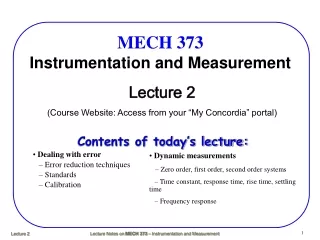
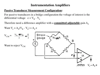
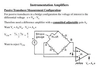
Instrumentation Amplifiers Passive Transducer Measurement Configuration : For passive transducers in a bridge configuration the voltage of interest is the differential voltage e = V B - V A Therefore need a difference amplifier with a committed adjustable gain A d

E N D
Instrumentation Amplifiers Passive Transducer Measurement Configuration: For passive transducers in a bridge configuration the voltage of interest is thedifferential voltage e = VB - VA Therefore need a difference amplifier with a committed adjustable gain Ad Want Vo = Ad(VB - VA) = Ad e VCM = Want to reject VCM R R+DR R R IA Vo = Ad e
Instrumentation Amplifiers: Active Transducer Measurement Configuration: For an active transducer the differential voltage e created by the transducer is of interest Therefore need a difference amplifier with a committed adjustable gain Ad Want Vo = Ad e Surface whose temperature is to be measured may be at some non-zero potential (VCM) relative to ground Want to reject VCM IA Vo = Ad e
Instrumentation Amplifiers: Transducer and Instrumentation Amplifier (IA) Circuit Model: • IA has a committed adjustable differential gain Ad • If e is the differential voltage of interest (vid) • Want Vo = Ade • Want a high CMRR to reject VCM • Want high Zin and low Zout • Zd is the differential input impedance (1 - 100 MW) • ZCM is the common mode input impedance (100 MW) • IA not an op-amp • Op amp open loop uncommitted gain • IA closed loop committed gain • IA has higher Zin and CMRR • IA has lower Vos and Ibias and drift with temperature • R1 and R2 are the source impedances of input transducer - R1 may not equal R2 IA
Instrumentation Amplifiers: Transducer (Sensor) and Instrumentation AmplifierCommon Mode Voltage Equivalent Circuit: Set e = 0 A B Unwanted parasitic differential voltage Vp produced by VCM due to imperfections in the transducer and/or transducer connections. If bridge is balanced Vp = 0 If bridge is not balanced Vp ≠ 0 Vp will contaminate Vo Vo≠ Ad e Vo = Ad (e + Vp) Therefore even if the IA has an infinite CMRR (i.e ACM =0)still have a common mode output voltage error
Instrumentation Amplifiers: Transducer (Sensor) and Instrumentation AmplifierCommon Mode Voltage Equivalent Circuit: Set e = 0 A B A Assuming the worst case imbalance: R1 = 0 Circuit becomes → Usually specified with a 1kWsource impedance imbalance B
Instrumentation Amplifiers: IA CMMR = A B Circuit CMRR = Increasing ZCM reduces Vp
Instrumentation Amplifiers: Differential Amplifier: (Single op-amp instrumentation amplifier) To obtain vo in terms of v1and v2 use superposition theorem
Instrumentation Amplifiers: Differential Amplifier: (Single op-amp instrumentation amplifier) Short input to v2(Inverting Configuration)
Instrumentation Amplifiers: Differential Amplifier: (Single op-amp instrumentation amplifier) Short input to v1(Noninverting Configuration)
Instrumentation Amplifiers: Differential Amplifier: (Single op-amp instrumentation amplifier) To obtain vo in terms of v1and v2 use superposition theorem
Instrumentation Amplifiers: Differential Amplifier: (Single op-amp instrumentation amplifier) Differential Input Impedance: Rin, Rid, Zid, Zd Zd = 2R1 Zd is limited
Instrumentation Amplifiers: Transducer and Differential Amplifier Circuit Model: External Circuit Instrumentation Amplifier Op Amp CMRR, Zd and ZCM are important attributes of an IA.
RS2 RS1 Ri2+ Rf2 Ri1+ Rf1 + Ro Instrumentation Amplifiers: Transducer and Differential Amplifier Common Mode Voltage Equivalent Circuit: A A D B B D D ZCM Can assume Ro = 0 CMRR, Zd and ZCM are important attributes of an IA.
Instrumentation Amplifiers: Three Op Amp Instrumentation Amplifier: CMRR and Zin are very important attributes of an IA Can increase Zin of difference amplifier configuration by adding unity gain buffers or buffers with gain
Instrumentation Amplifiers: Three Op Amp Instrumentation Amplifier: CMRR and Zin are very important attributes of an IA Can increase Zin of difference amplifier configuration by adding buffers Common mode signals are not amplified if common R1 is used and connection to ground is removed.
Instrumentation Amplifiers: Transducer and Three Op Amp IA Circuit Diagram: External Circuit Instrumentation Amplifier